Installation Guide
Rio Rancho, NM 17
The following are assumed:
• A POTS line has already been connected to the
DMTH4 rear panel Telephone Line jack
• The DMTH4 has been connected to the DM1624
via the DANI bus
• The microphones and overhead speakers are
already connected to the DM1624 in a Mix-Minus
configuration.
The result will be that when a person talks into Mic 1 in
Conference Room 1, they will be heard both in Confer-
ence Room 1 and in Conference Room 2. Likewise, if a
person in Conference Room 2 talks into one of the
microphones in that room, they will be heard both
Conference Room 2 and Conference Room 1.
The following discusses setting up a DM Series consist-
ing of a DM1624 Digital Automixer and a DMTH4 Digital
Telephone Hybrid on near end of the telephone connec-
tion. The same process is used to set up the DM
Series at the other far end of the telephone connection.
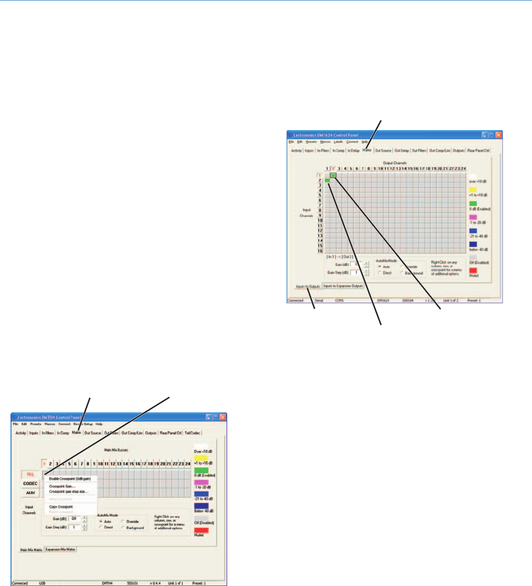
Setting up the DMTH4 Main Matrix
The TEL Input needs to be configured so that it is
connected to DANI Bus Mix Busses 1 and 2. (See
Conference Room Signal Flow Diagram.)
1.) Select the Matrix Tab in the DMTH4 Control Panel,
then select the “Main Matrix” sub tab. Right click the
TEL input to Mix Bus 1 crosspoint and select
“Enable Crosspoint” from the popup menu
2.) Repeat Step 1 for Mix Bus 2.
Setting up the DM1624 Main Matrix
The DM1624 Main Matrix needs to be configured so the
microphone inputs are connected to the output chan-
nels used to drive the local sound reinforcement
speakers. These inputs will be mixed together with the
audio received from the DMTH4 TEL Input. Both local
audio and audio from Conference Room 2 are heard on
Matrix Tab
Input Channel 2 to
Output Channel 1
Input Channel 1 to
Output Channel 2
Inputs to
Outputs Tab
the speakers in Conference Room 1. (See Conference
Room Signal Flow Diagram.)
1.) Select the Matrix Tab on the DM1624 Control
Panel, then select the “Inputs to Outputs” sub tab.
2.) Right click the Input Channel 1 to Output Channel 2
crosspoint and select “Enable Crosspoint” from the
popup menu.
3.) Right click the Input Channel 2 to Output Channel 1
crosspoint and select “Enable Crosspoint” from the
list.
Setting up the DM1624 Expansion Matrix
Once the DM1624 Main Matrix has been set up, the
DM1624 Expansion Bus Matrix needs to be configured
so the local audio is sent back to the DMTH4 for
distribution to the remote Conference Room (Confer-
ence Room 2 in this example). (See Link Conference
Rooms with a DMTH4, Example Setup and Conference
Room Signal Flow Diagram.)
1.) Select the Inputs to Expansion Outputs Tab in the
DM1624 Matrix Tab.
2.) Right click the Input Channel 1 to Expansion Out
Channel 1 crosspoint and select “Enable
Crosspoint” from the popup menu.
3.) Right click the Input Channel 2 to Expansion Out
Channel 1 crosspoint and select “Enable
Crosspoint” from the popup menu.
Click on Crosspoint Button
Setting up DMTH4 Main Matrix
Matrix Tab
