Page 19
724-746-5500 | blackbox.com
Appendix D: DDC Modes
D. DDC Modes
The Multi DVI System features the ability to send DDC display identifiers to the
video source to determine display capabilities. The DDC is a data communications
channel used in plug-and-play devices to accurately report a display’s capabilities
and identify the manufacturer. If this data is not available, the video source may
revert to a low resolution or not display at all.
The Multi DVI features the ability to report a Universal Display (MRI Magic Display)
that supports most popular VESA standards in standard or widescreen formats as
well as the ability to clone an actual display’s DDC information that is attached to
either the local DVI output of the transmitter or a receiver’s DVI output.
The various modes are detailed below:
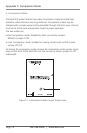
Mode 1: Universal Display (MRI Magic Display) (DEFAULT)
This mode reports a generic display supporting popular screen formats
and is suitable for most if not all display types.
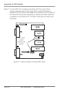
Mode 2: Clone DDC from DVI Output of transmitter
This mode copies the DDC from a display attached to the local output
of the transmitter.
Mode 3: Clone DDC from receiver (first one if using daisychain options)
This mode copies the DDC data from a display attached to the
receiver (first receiver if a daisychain mode is in use).
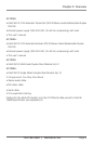
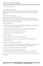
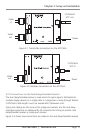
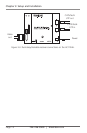
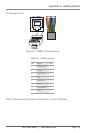
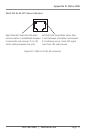
Changing modes requires internal jumpers to be changed. See Figure D-1 for-
jumper locations (settings are stored in non-volatile RAM and are not lost when
power is removed):
Mode 1: To restore, install jumper J20 while transmitter is powered on. No other
cable connections need to made.
Mode 2: To clone DDC from a display connected to the local DVI output of the
transmitter, Install a jumper on J9 and J20 while transmitter is powered
off, then connect the display to the transmitter and power it on. Remove
J20 while transmitter is powered on and leave J9 in. The video source
does not need to be connected.