


CS6X
28
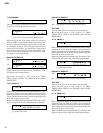
T21. A-D LEVEL, JACK
Set the A/D GAIN volume to the maximum level.
Input a 1 kHz sine wave of the following level through the
A/D input port according to the instructions on the LCD.
MIC: -40 dBm ±0 dBm LINE: -6 dBm ±0 dBm
When a plug is connected to the jack, both “EXTRACT
PLUG” appears and the A/D level appear.
When a plug is not connected and the level is 2 or lower,
“INSERT PLUG” appears and when a plug is inserted,
the A/D level will be indicated.
“OK” will appear when the AD level is within the
following range.
MIC: 75 or greater and 85 or less
LINE: 75 or greater and 85 or less
When MIC is OK, the LINE check will be executed
automatically.
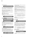
xxx
,
yyy
display
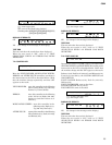
DISPLAY OF RESULTS
OK
NG
TEST END
When the [EXIT] switch is pressed, the sound output
will stop and the next test number will be set.
For the procedure to take when the test result is “NG”,
refer to “C. TEST SELECTION WHEN AN ERROR HAS
BEEN DETECTED”.
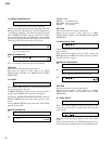
T22. A/D -> D/A
This test is used to check the signal passage from the A/
D input to the D/A output.
(GAIN is set to LINE 1 in the initial settings.)
Input a 1 kHz ±5 Hz, -6.0 dBm ±0 dBm sine wave signal
to each signal passage through the A/D input in the order
described below. Check that the output level specified
below is obtained at the output L and R respectively.
Set the A/D INPUT VOLUME knob to the Max position.
LINE 1, LINE 2, MIC 1 and MIC 2 can be selected by
using [DEC] and [INC].
With LINE 1, GAIN = LINE applies and the signal input
through the A/D will be output at the D/A as is.
With LINE 2, GAIN = LINE applies and the level of the
signal input through the A/D will be lowered to the
specification of the main unit (-12dB) and then output
at the D/A.
With MIC 1, GAIN = MIC applies and the signal input
through the A/D will be output at the D/A as is.
With MIC 2, GAIN = MIC applies and the level of the
signal input through the A/D will be lowered to the
specification of the main unit (-12dB) and then output
at the D/A.
When GAIN = Line 1, move the A/D INPUT VOLUME
knob and check that the sound volume varies.
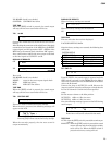
OUTPUT-L: 1 kHz ±5 Hz, sine wave, +15.0 ±2 dBm (10k
ohm load) (Distortion: 1.00% or less)
OUTPUT-R: 1 kHz ±5 Hz, sine wave, +15.0 ±2 dBm (10k
ohm load) (Distortion: 1.00% or less)
TEST END
When the [EXIT] switch is pressed, the sound output
will stop and the next test number will be set.
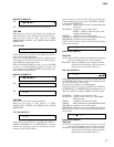
T23. PLUG-IN1
T24. PLUG-IN2
Connect the HARMONY PLUG-ON boarding into the
PLUG-IN 1 slot.
After checking the connection of the PLG-IN 1 slot, the
signal transmission and reception of the CONTROL
LINE, and the IN/OUT of the MIDI LINE and MEL
LINE, check to ensure that the output level specified
below is obtained at output L and R respectively.
Set the MASTER VOLUME knob to the Max position.
OUTPUT-L: 1 kHz ±5 Hz, sine wave, +11.5 ±2 dBm (10k
ohm load) (Distortion: 1.00% or less)
OUTPUT-R: 1 kHz ±5 Hz, sine wave, +11.5 ±2 dBm (10k
ohm load) (Distortion: 1.00% or less)
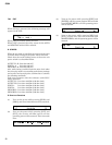
DISPLAY OF RESULTS
OK (No change in the message on display)
NG
xxxxxxx
: Error code
Error code
NG-BOARD: a board other than the VH board is loaded.