


CS6X
27
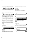
DISPLAY OF RESULTS
OK
NG (No change in the message on the display)
TEST END
When the test results of all switches are satisfactory,
“OK” will appear on the LCD and the testing will end.
When the test result is “NG”, refer to “C. TEST
SELECTION WHEN AN ERROR HAS BEEN
DETECTED”.
T18. TO HOST
Connect pin No.3 to pin No.5, and connect pin No.6 to
No.8, and then execute testing.
Operate the HOST SELECT switch according to the
instruction on the LCD and check that “OK” appears
when [MIDI] is reached at the end.
When the HOST SELECT switch is set to the MIDI
position, the “SET HOST Sw [MAC]” message will
appear. Next set the HOST SELECT switch of the main
unit to MAC to begin testing.
DISPLAY OF RESULTS
OK
NG
(When unexpected data is received)
NG
(When reception is not completed within the specified time)
TEST END
The test ends after the result is displayed.
When the test result is “NG”, refer to “C. TEST
SELECTION WHEN AN ERROR HAS BEEN
DETECTED”.
T19. 1kHz OUTPUT-L
Insert plugs into OUTPUT-L, OUTPUT-R, INDIV-1,
INDIV-2, PHONES (L), and PHONES (R), and then
connect the frequency counter, oscilloscope and AC
voltmeter (with a JIS-C filter).
Set the master volume to Max and check that the
following signals are output from OUTPUT-L, INDIV-
1 and 2, and PHONES (L).
OUTPUT-L: 1 kHz ±1.5 Hz, sine wave, +6.0 ±2 dBm (10k
ohm load)
OUTPUT-R: -72 dBm or less (10 kohm load)
INDIV-1: 1 kHz ±1.5 Hz, sine wave, +6.0
±2 dBm (10 kohm load)
INDIV-2: -72 dBm or less (10 kohm load)
PHONES (L): 1 kHz, sine wave, +5.0 ± 2 dBm (33 ohm load)
PHONES (R):-64 dBm or less (33 ohm load)
While sound is being output, the following message
appears on the LCD.
DISPLAY OF RESULTS
TEST END
AUTO: when the [INC] switch is pressed, the sound output
will stop and the next test will be executed.
MANUAL: when the [EXIT] switch is pressed, testing
will end, the initial display will be restored
and the next test number will be set.
T20. 1kHz OUTPUT-R
Insert plugs into OUTPUT-L, OUTPUT-R, PHONES (L),
and PHONES (R), and then connect the oscilloscope and
AC voltmeter (with a JIS-C filter).
Set the master volume to the Max position.
Check that signals are output at OUTPUT-L, OUTPUT-
R, PHONES (L), and PHONES (R) as described below. At
this time, signals are output at MEL for mLAN as well.
OUTPUT-L: -72 dBm or less (10k ohm load)
OUTPUT-R: 1 KHZ ±1.5 Hz, sine wave, +6.0 ±2 dBm
(10k ohm load)
INDIV-1: -72 dBm or less (10k ohm load)
INDIV-2:
1 kHz ±1.5 Hz, sine wave, +6.0 ±2 dBm (10k ohm load)
PHONES (L): -64 dBm or less (33 ohm load)
PHONES (R): 1 kHz, sine wave, +5.0 ±2 dBm (33 ohm load)
While sound is output, the following message appears
on the LCD.
DISPLAY OF RESULTS
TEST END
AUTO: when the [INC] switch is pressed, the sound
output will stop and the next test will be executed.
MANUAL: when the [EXIT] switch is pressed, testing
will end, the initial display will be restored
and the next test number will be set.