


11
Unit Operation
In Occupied mode, the controller
operates according to the occupied
setpoints. In Occupied Standby
Mode, the unit controller operates
according to the Occupied Standby
setpoints. When the controller
receives a communicated
unoccupied request, the controller
operates according to the
unoccupied setpoints regardless of
the state of the hardwired
occupancy input.
If neither the binary input nor the
communicated input is used to
select the occupancy mode, the
controller defaults to occupied
mode because the occupancy binary
input (if present) typically is
configured as normally open
without an occupancy device
connected.
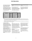
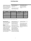
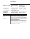
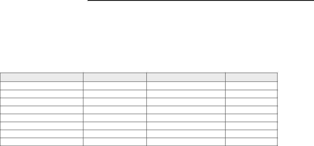
Table 4: Normally open hardwired input configuration (BI 3)
Description Communicated Request Hardwired State Result
Standalone NA Open = Occupied Occupied
Standalone NA Closed = Unoccupied Unoccupied
Communicating Occupied Open = Occupied Occupied
Communicating Unoccupied Open = Occupied Unoccupied
Communicating Occupied Standby Open = Occupied Occupied Standby
Communicating Occupied Closed = Occupied Standby Occupied Standby
Communicating Unoccupied Closed = Occupied Standby Unoccupied
Communicating Occupied Standby Closed = Occupied Standby Occupied Standby
Generic Binary Input
Building automation systems can
monitor the status of the generic
binary input. This input does not
affect controller operation.
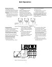
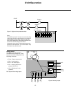
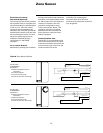
High and Low Pressure
Switches
The high and low pressure cutout
switches are wired in series with the
compressor contactor in the unit.
The ZN510 controller detects the
state of each switch circuit by
monitoring the controller’s
compressor triac outputs. If either
the high pressure switch (HPC) or
the low pressure switch (LPC) switch
opens, a fault condition occurs. This
open circuit prevents the
compressor contactor from
energizing keeping the compressor
from running. The controller
automatically detects the fault
condition by measuring the
compressor triac output signal.
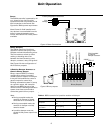
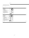
By default, when the HPC or LPC
switches detect a high or low
pressure condition in the refrigerant
circuit, the special input detects the
diagnostic and disables all
compressor operation for that
circuit. The unit fan continues to
operate, if only one circuit is
disabled in a two compressor unit.
When the HPC/LPC diagnostic is
present on both circuits, the ZN510
shuts off the unit fan and disables
unit operation. See Figure 7 for high
and low pressure switch.
When the refrigerant circuit returns
to normal, the HPC and the LPC
switches automatically reset. The
high or low pressure cutout
diagnostic may need to be manually
reset to clear the diagnostic and
enable compressor operation for the
fault circuit.
Note:
If configured for normally closed, all states are opposite of Table 4.