


Pre - installation
B. Installation Steps
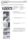
B-1. Remove the cover of an empty 3.5’’ external drive bay.
Switch off the system power and open the case side panel.
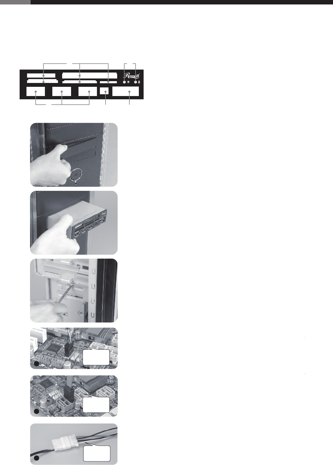
B-4. Connect the internal USB, SATA connectors to the
corresponding motherboard headers. Connect the power
4-pin molex connector to the PSU peripheral connector.
NOTE: If the connectors are not apparent on the board consult
your motherboard manual. Connecting the panel to the
wrong headers may result in motherboard damage.
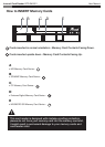
B-2. Insert the Internal card reader into the drive bay until it is
in line with front panel of the chassis.
B-3. Secure the card reader with the screws provided or the
case 3.5" mounting system.
A
B
C
PSU 4-pin
molex
connector
USB 10-pin
header
SATA
connector
A
B-1
B-2
B-3
B-4
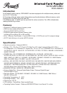
A. Card Reader
a. 5 x memory card reader slots
b. 3 x external USB 2.0 port
c. 2 x LEDs
e. DC 5V output port
f. eSATA
Contents
• Card reader/writer
• Black and silver front panels
• DC to DC Cable
• Screws
• User manual
MS/MSPro/MS Duo/MS Pro Duo
CFI/CFII/MD
Extreme Digtal M2 / Micro SD
SD/MMC/RS MMC
USB 2.0 USB 2.0 USB 2.0
DC 5V
eSATA
b
e f
a c
WARNING
Electrostatic discharge (ESD) can damage system components. Use an ESD controlled workstation. If such a
workstation is not available, wear an antistatic wrist strap or touch an earthed surface before handling any PC
components.
Internal Card Reader RCR-IM5001 User Manual