


20
Parker Hannifin Corporation
Open-Center Directional Control Valve
VO40
Catalog HY17-8505/UK
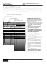
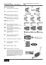
[62] – Piston Head Side of Cylinder
The default for this field is code M. Codes A and B are only used when asymmetrical spools must be developed.
For example, a cylinder that requires meter-in for one direction and meter-out for the other.
M Standard symmetrical spool- cylinder or motor.
A Piston head connected with port “A”.
B Piston head connected with port “B”.
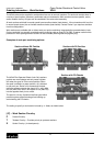
[76 A/B] – Work Port Valves
This pertains to the work port accessory options.
/ Port not machined.
Y2 Relief Valve cavity plugged.
N2 Anti-cavitation valve.
( ) RV/AC Non-Adjustable: Enter Pressure setting (PSI or Bar).
Note: RV Set at 10 LPM (2.6 GPM).
C2 Pilot-Operated Checks (Lock-out valve).
Refer to page 16.
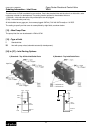
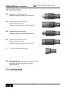
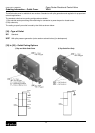
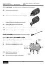
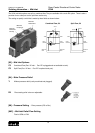
[88 A/B] – Work Port Option
/ No Restrictor.
Work port restrictors restrict flow in one direction
and are free flow in the opposite direction.
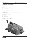
[90] – Spacer Section
N Spacer Section.
This section connects the open center, parallel path
and tank cores between two adjacent work sections.
This section is used to provide additional spacing
between two work sections. All other fields in the
work section code can be left blank. (Contact Parker
for size options available.)
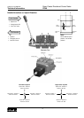
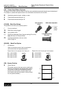
Anti-Cavitation
Check
TANK
OPEN
CENTER
PARALLEL
PATH
TANK
OPEN
CENTER
PARALLEL
PATH
Y plug for blocking
RV cavity
RV/AC Non-Adjustable
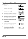
Restrict flow “out” of actuator “into” work port.
P1 = 1mm (0.040")
P2 = 2mm (0.080")
P3 = 3mm (0.120")
P4 = 4mm (0.160")
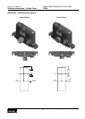
Restrict flow “out” of work port “into” actuator.
N1 = 1mm (0.040")
N2 = 1mm (0.080")
N3 = 1mm (0.120")
N4 = 1mm (0.160")
ACTUATOR
METER OUT
FREE
ACTUATOR
METER IN
FREE
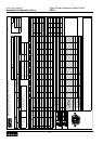
Ordering Information – Work Sections