


10
Parker Hannifin Corporation
Open-Center Directional Control Valve
VO40
Catalog HY17-8505/UK
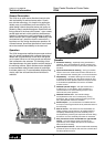
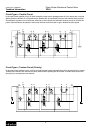
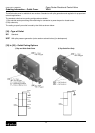
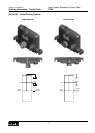
How to Order the VO40 Valve Assembly
A specification sheet is located in the back of this book, and is also available in an electronic Excel format on our
web site. This form should be used to configure a valve assembly. The layout starts from the inlet cover on the left,
work sections and mid-inlets in the middle and the outlet cover on the far right. Each field will require an entry, and
the fields are represented with a position reference [ ] to help guide you to the option codes listed in the catalog
pages 11 to 21.
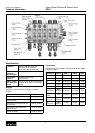
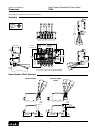
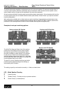
Example: Inlet Cover (Sect #1)
Customer has 23 l/min pump flow, requires
a pilot operated main relief set 140 bar and
wants all SAE-8 work ports.
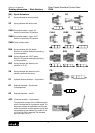
• Reference position [4] calls out the thread
option for the entire valve assembly (SAE
or BSP) (“U8” is the code for all SAE-8
size ports).
Note: There is a separate specification
sheet which utilizes metric units.
• Reference position [12] calls out the
system flow and can be listed in LPM or
GPM depending on which spec sheet you
are using (23 is entered for flow).
• Reference position [15] gives you an
option for a standard type inlet “I” or
an unloader type inlet cover “IU” (“I” is
entered for std inlet cover).
• Reference position [16] indicates the type
of main relief valve: (“PB” is the code for
a pilot operated RV).
• Reference position [17] Enter desired
relief valve setting (140 bar is entered).
• Reference position [17C] Enter desired
flow for relief valve setting (23 l/min is
entered).
• Reference position [24-27] calls out the
inlet/outlet porting (machined/plugged)
options:
T1 is the top tank port open.
T2B is code for side tank port plugged.
P1B is code for top inlet port plugged.
P2 is code for top inlet port open.
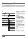
Inlet Cover Portion of Spec Sheet
23
23
PB
I
140
T1
T2B
P1B
P2
STATE:
FILLED BY:
# 1 # 2
pos pos description
12 47 Circuit type
15 50
Spool actuator
16 51 Lever Bracket / handle
17 51C Clevis or Handle location
17C 52 Spool pos.indication
24 60 Spool function
25 62 Piston head side
26 76A
Port A valve
27 76B
Port B valve
88A Restrictor on port A
88B
Restrictor on port B
90 Spacer Section
93 Mid Inlet type
94 Main relief valve
98
Pressure setting (PSI)
98C Relief Flow Setting (GPM)
P/N SECTION
P/N MCH. CAST
SPACER SECTION
MID INLET
Tank connection T2
Pump connection P1
Pump connection P2
Pressure setting (PSI)
Relief Flow Setting (GPM)
Tank connection T1
Type of Inlet
Main relief valve
description
Max.Inlet flow (GPM)
STACK POS
INLET
WORK SECTION
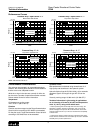
[04]
CONNECTIONS
THREAD
G = ALL PORTS 3/8" BSP
U = ALL PORTS 9/16" UNF (SAE #6)
U8 = ALL PORTS 3/4" UNF (SAE #8)
U6 = P ANDT 3/4" UNF AND WORK PORTS 9/16" UNF
DATE:
CITY:
CUSTOMER
U8
Customer Information
Code Position Reference
Section Number
starting with the Inlet Cover
Ordering Information