


KRAMER: SIMPLE CREATIVE TECHNOLOGY
Defining the RC-53D
4
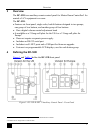
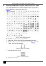
Table 1: RC-53D K-NET™ Auxiliary Control Panel – Front Panel Features
# Feature Function
1 SOURCE Buttons Group of four programmable, backlit buttons
1
2 Faceplate Screws Four screws connecting the faceplate to the Rear Box
3 “DISPLAY” and “SOURCE”
Labels
Programmable, 8 character, LCD displays on a blue background
4 DISPLAY Buttons Group of two programmable, backlit buttons
5 Maximum VOLUME LED Lights red, indicating maximum volume
6 VOLUME LEDs Light green, indicating volume level
7 VOLUME Knob Rotate clockwise to increase volume level
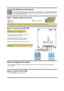
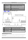
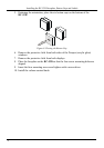
Figure 2 and Table 2 define the RC-53D rear panel.
Figure 2: RC-53D K-NET™ Auxiliary Control Panel – Rear Panel
Table 2: RC-53D K-NET™ Auxiliary Control Panel – Rear Panel Features
# Feature Function
1 Program USB Connector Connect to a computer for firmware upgrade
2
2 Grounding Screw Connect to grounding wire
3 RS-232 Terminal Block For factory use only
4 K-NET Terminal Block Connect the GND to the Ground connection
3
, connect B (-) and
A (+) to RS-485, and connect +12V to +12V on the companion
unit
5 K-NET Terminal Block
1 By the system integrator only
2 When the unit is connected via K-NET to a Master Room Controller, you can upgrade the firmware via the USB or ETH ports of the
Master Room Controller
3 The ground connection is sometimes connected to the shield of the RS-485 cable (in most applications, it is not connected)