


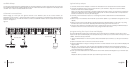
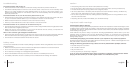

Power/Standby Press to turn the Control Center power On and Off. The Power/Standby LED will
illuminate green when the power is on and red when the unit is in standby mode
Input Channel Each Input Channel name can be programmed in order to identify the AV device that
Display is connected to each Input Channel
Input Selector Press to page through and select the required Input Channel
IR Remote Receiver For use with the Remote Control
Display Setting These controls are used to program the Input Channel names
Controls displayed on the LCD Display
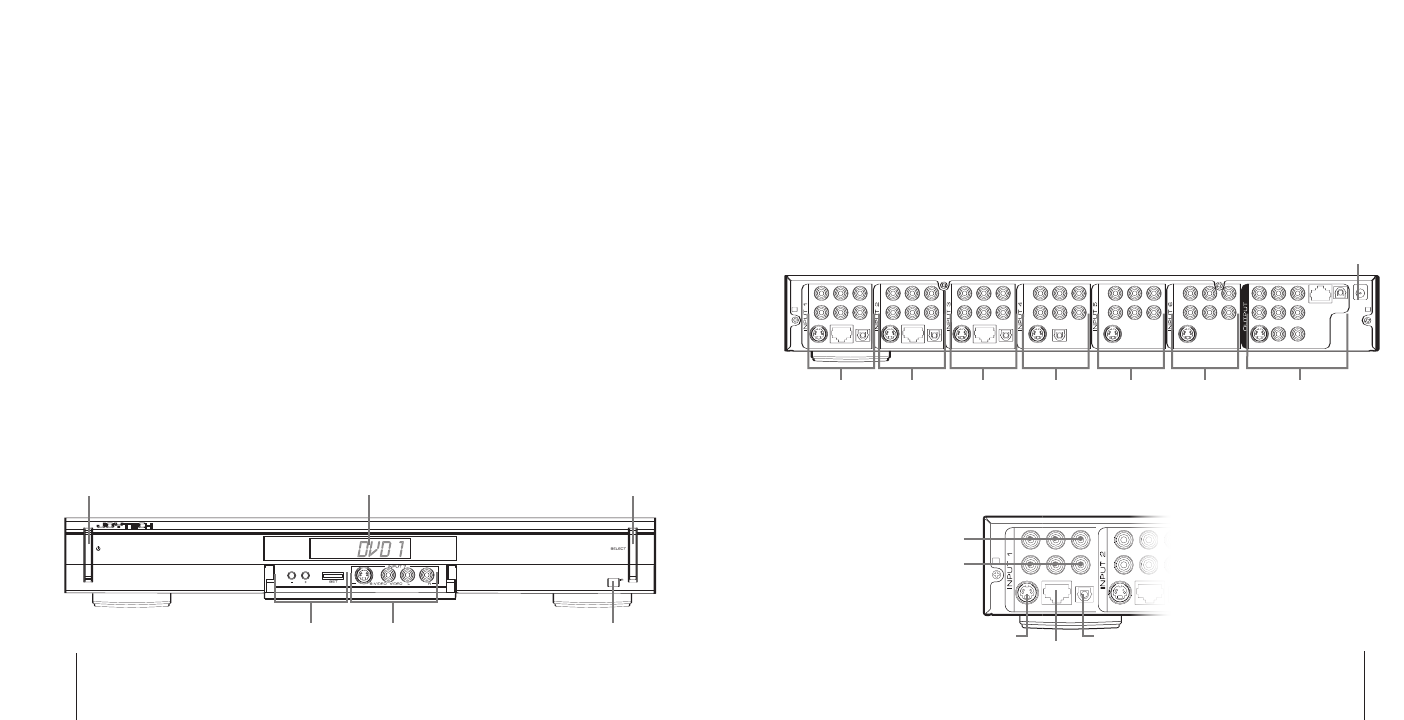
Input 7 Primarily used for temporary connection of camcorders and other AV devices to the
Control Center
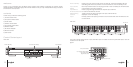
rear view
The Control Center has a total of 7 Input Channels. Input 7 is located on the front panel and Inputs 1 to 6 are
located on the rear panel.
figure 1
3
english
english
english
welcome
Thank you for purchasing the JOYTECH Control Center 240C. Before connecting the Control Center,
please familiarize yourself thoroughly with this User Guide so that you fully understand the setup procedure
and functions of the product.
contents
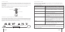
Check that you have the following items:
1) Control Center 240C
2)Component Video Cable
3)Audio Cable
4)S-Video/Audio Cable
5)Composite/Audio Cable
6)Ethernet Cable
7)DC Power Adapter
8)Remote Control
9)User Guide
Control Center layout
front view
2 english
Power/Standby
Input Channel Display Input Selector
IR Remote Receiver
DC 12V IN
Input 1
Ethernet
(RJ45)
S-Video
Digital Optical Audio
Input 7Display Settings
Controls
Input 2 Input 3 Input 4 Input 5 Input 6 Output
Component Video
Composite Video (yellow)
Left Audio (white)
Right Audio (red)