


13
GB
Only use permitted extension cables.
Ask your electrician.
Keep the extension cable away from the area
you are cutting.
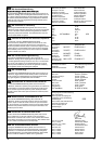
The mains voltage and the equipment voltage
stated on the type plate must be the same. If
extension cables are used, these must comply
with the minimum cross-sections in the table
below:
Voltage Cable Cross-
length section
220-240V/ 50Hz Up to 20 m 1.5 mm
2
220-240V/ 50Hz 20 - 50 m 2.5 mm
2
A brief voltage dip may occur when you switch
on your electric lawnmower (due to conditions
of the power supply) that may affect other
devices (e.g. a lamp may flicker).
This problem should not occur with supply
impedances of Z
max
< 0,46 Ohm.
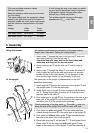
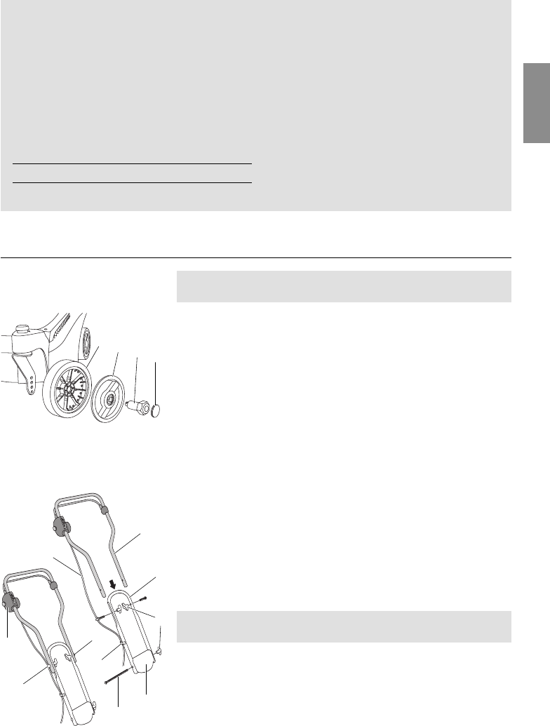
3. Assembly
All 4 wheels must always be screwed in at the same cutting
height (see 4 Operation “Setting the cutting height”).
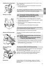
1. Insert screw
1
through the bore in the hub cap
2
and push
the 6-sided head fully into the hub cap
2
.
Use wheel hub with short bolt for the front wheel and
wheel hub with long bolt for the rear wheel.
2. Press covering cap
3
into the hub cap
2
until it snaps in
place.
3. Insert screw
1
through the wheel
4
and screw the wheel
4
firmly in place by hand at the side and ensure it is securely
located.
Screw in the small wheels (13 cm diameter) at the
front and the large wheels (16 cm diameter) at the rear.
The upper part of the upright is preassembled on the 34 E
basicMove lawnmower.
1. Insert long bolt
5
through the lower part of the upright
6
and
the upright holder
7
from the cable side.
2. Screw lower part of upright
6
firmly in position with the wing
nut
8
. During this process, the wing nut
8
must be on the
opposite side to the cable
9
.
3. Push upper part of upright
0
into the grooves in the side of the
lower part of the upright
6
until the bores in the upper part
0
and lower part
6
of the upright match precisely.
Check positioning of the plug switch
D
. The cable
9
must run
along the side of the upright and must not cross over itself.
4. Push short bolt with cable guide
A
on the cable side from
outside through the bore
0
in the upper part of the upright
0
.
5. Push short bolt without cable guide
B
from outside through
the bore in the upper part of the upright
0
.
6. Place both wing nuts
8
on the bolts
A
/
B
and tighten firmly.
7. Press cable
9
into the short bolt with cable guide
A
and
fasten to the lower part of the upright
6
with the cable clip
C
.
Fitting the wheels:
Fit the upright:
3
1
2
4
B
A
9
C
D
5
7
0
6
8