


En-5
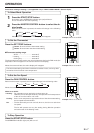
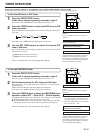
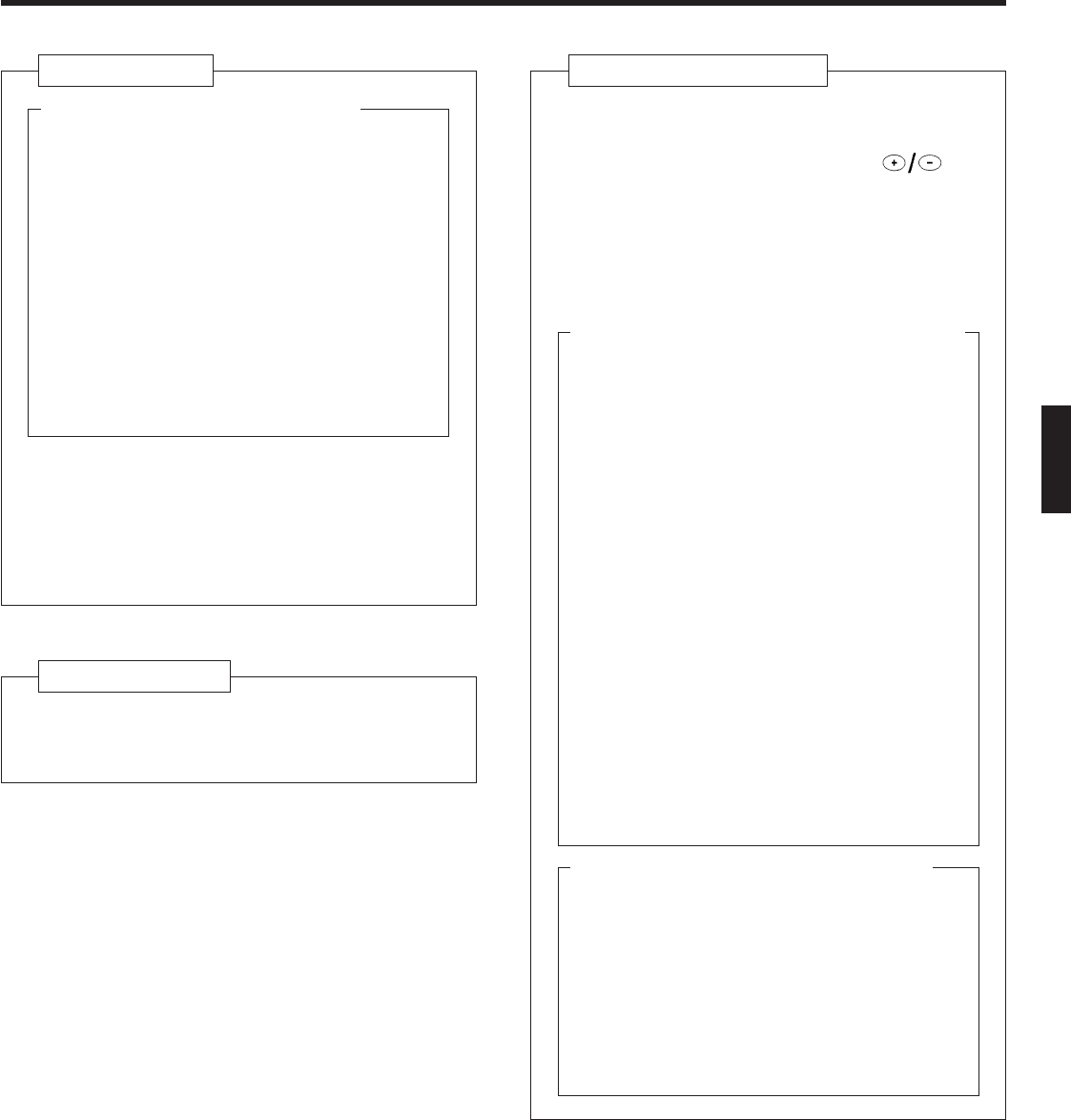
Fig. 5 Remote Control Unit
F SLEEP Button
G MASTER CONTROL Button
H SET TEMP./SET TIME Buttons ( )
I Signal Transmitter
J TIMER Button
K FAN CONTROL Button
L START/STOP Button
M Battery compartment lid
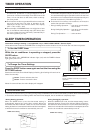
Inside of the battery compartment lid (Fig. 6)
N AIR FLOW DIRECTION Button
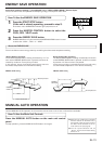
O ENERGY SAVE Button
P CODE CHANGE (Slide Switch)
Switching the remote control unit code.
(Max. 4 units)
Q TIME ADJUST Button
R TEST RUN Button
● This button is used when installing the air
conditioner and should not be used under
normal conditions as it will cause the air
conditioner’s thermostat function to oper-
ate incorrectly.
● If this button is pressed during normal op-
eration, the unit will switch to test opera-
tion mode, and the indoor unit’s OPERA-
TION indicator light and TIMER indicator
light will begin to flash simultaneously.
● To stop the test operation mode, either
press the TEST RUN button once again, or
press the START/STOP button to stop the
air conditioner.
S ACL Button
T Remote Control Unit Display (Fig. 7)
U Transmit Indicator
V Clock Display
W Operating Mode Display
X Timer Mode Display
Y Fan Speed Display
Z Temperature Set Display
[ Timer Set Indicator
\ Temperature Set Indicator
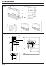
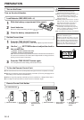
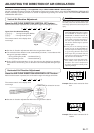
Fig. 1 Indoor Unit
1 Operating Control Panel (Fig. 2)
2 MANUAL AUTO button
3 Remote Control Signal Receiver
4 OPERATION Indicator Light (red)
5 TIMER Indicator Light (green)
6 SWING Indicator Light (orange)
(VERTICAL SWING)
7 SWING Indicator Light (orange)
(HORIZONTAL SWING)
● If the TIMER indicator light flashes when
the timer is operating, it indicates that a
fault has occurred with the timer setting
(See page 17 Auto Restart).
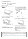
8 Intake Grille (Fig. 3)
9 Air Filter
0 UP/DOWN Air Direction Flaps
A RIGHT/LEFT Air Direction Louvers
(behind UP/DOWN Air Direction Flaps)
B Drain Hose
Fig. 4 Outdoor Unit
C Intake Side
D Outlet Side
E Pipe Unit