


A-3
a.Perform turn-on checkout procedure given in page 1-7.
b.Perform the CV and CC Load Regulation perfor-
mance tests given in the following paragraphs
respectively.
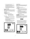
PERFORMANCE TESTS
The following paragraphs provide test procedures for verify-
ing the power supply's compliance with the specifications of
Table 1. Please refer to adjustment and calibration or trouble-
shooting procedure if you observe any out of specification
performance.
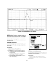
Measurement Techniques
Setup for All Tests.
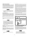
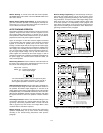
Measure the output voltage directly at the
+S and -S terminals on the rear panel; in this way the monitoring
device sees the same performance as the feedback amplifier
within the power supply. Failure to connect the monitoring device
to the proper points shown in Figure A-3 will result in the mea-
surement not of the power supply characteristics, but of the
power supply plus the resistance of the leads between its output
terminals and the point of connection.
Use separate leads to all measuring devices to avoid the sub-
tle mutual coupling effects that may occur between measur-
ing devices unless all are returned to the low impedance
terminals of the power supply. Twisted pairs or shielded cable
should be used to avoid pickup on the measuring leads.
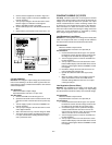
Electronic Load.
The test and calibration procedures use an
electronic load to test the supply quickly and accurately. An
electronic load is considerably easier to use than load resis-
tor. It eliminates the need for connecting resistors or rheostats
in parallel to handle the power, it is much more stable than
carbon-pile load, and it makes easy work of switching
between load conditions as is required for the load regulation
and load transient response tests.
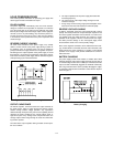
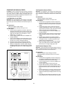
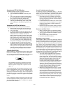
Current Monitoring Resistor Rs.
To eliminate output-current
measurement error caused by voltage drops in the leads and
connections, connect the current monitoring (sampling) resis-
tor between -OUT and the load as a four-terminal device. Fig-
ure A-3 shows correct connections. Connect the current
monitoring test leads inside the load lead connections directly
at the monitoring resistor element. Select a resistor with sta-
ble characteristics and lower temperature coefficient (see
Table A-1).
Figure A-3. Current Monitoring Resistor Connections
* P = Performance testing A = Calibration adjustments T = Troubleshooting.
Table A-1. Test Equipment Required
TYPE REQUIRED CHARACTERISTICS USE RECOMMENDED MODEL
Oscilloscope Sensitivity : 1 mV
Bandwidth : 20 MHz/100 MHz
Input : Differential, 50 ohm and 100 ohm
P, T Agilent 54600A
RMS Voltmeter True rms, 20 MHz bandwidth
Sensitivit
y : 1 mV
Accuracy : 5%
P
Multimeter Resolution : 100 nV
Accuracy : 0.0035%
P, A, T Agilent 34401A
Electronic Load Volta
ge Range : 240 Vdc
Current Range : 10 Adc
Open and short switches
Transient on/off
P Agilent 6063A
Load Resistor (R
L
) 1.3 ohm 60 W, 6.6 ohm 60 W, 20.5 ohm 60 W,
60 ohm 60 W
P
Current Monitoring
(Sampling) Resistor (R
S
)
0.1 ohm 0.1% 10 W, 1 ohm 1% 5 W P, A
Variable Volta
ge
Auto Transformer
Range : 85-130 and 200-260 Volts P, T