Troubleshooting 31
3
Troubleshooting
Shock Hazard: Most of the procedures in this chapter must be performed with power applied and
protective covers removed. These procedures should be done only by trained service personnel aware of
the hazard from electrical shock.
This instrument uses components that can be damaged or suffer serious performance degradation due to
ESD (electrostatic discharge). Observe standard antistatic precautions to avoid damage to the
components (see Chapter 1).
Introduction
Localizing the Problem
This chapter provides troubleshooting and repair information for the power supply. Before beginning troubleshooting
procedures, make certain the problem is in the power supply and not with an associated circuit, the GPIB controller (for
GPIB system power supplies), or ac input line. Without removing the covers, you can use the Verification tests in Chapter 2
to determine if the power supply is operating normally.
Chapter Organization
The information in this chapter is organized as follows:
Topic Information Given
Test Equipment Required Equipment required for completing all the tests in this chapter.
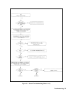
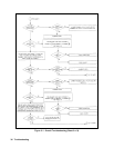
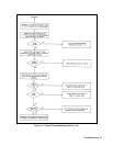
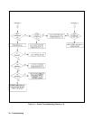
Troubleshooting Procedures A series of flow charts for systematic location of defective boards, circuits, and
components. An explanation of the error codes and messages generated during the
power-on selftest. Signature analysis techniques for troubleshooting the digital circuits
on the front panel, primary GPIB, and secondary interface circuits. Specific
paragraphs for:
• Checking the bias and reference supplies.
• Troubleshooting the CV/CC status annunciators.
• Troubleshooting the A3 FET board.
Post-Repair Adjustments Calibration and EEPROM initialization procedures required after the replacement of
certain critical components.
Disassembly Procedures Gaining access to and/or replacing components.


