


Users’ Guide: Networked Receiver Controller - NRC-2.0.1 PAGE 6
11
th
October 2005 Copyright © 2005 Aegis, Inc wwww.aegis-inc.net [ph. 240-568-9006]
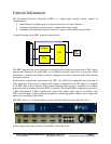
Channel Architecture
A channel defines a virtual connection between a client application and a receiver connected to
the NRC.
There are two types of channel connections which can be established to a receiver; a Primary
connection and a Piggy-back connection.
1. A Primary Connection
a. A Primary connection is established with a receiver when the receiver is free of
any other client connections.
b. A Primary connected client has full access and control of the receiver and its
resources.
2. Piggy-back Connection
a. A Piggy-back connection is established with a receiver when the receiver
currently has one or more other clients already attached to it.
b. A Piggy-back connected client cannot change any of the receivers settings,
although it can view the current receiver settings, and capture and format the
receivers audio output.
The NRC supports one Primary connection per receiver and multiple Piggy-back connections,
with the NRC able to support an aggregate of 64 simultaneous Primary/Piggy-back connections.
Audio Data Capture
The NRC uses an 8 channel PCI-based Analog/Digital converter card to digitize each receiver’s
audio output signal. Each receiver’s audio signal is digitized into 16-bit samples (14.8 effective
bits/sample) at a sampling rate of 16 KHz.
Each client attached to the receiver can receive a copy of this sampled audio data through a
simply packet based protocol, and can specify:
• the number of samples to be contained within a data packet
• the effective sampling rate of the data - either 8 KHz or 16 KHz.
• the audio data filtering option – 4 KHz LPF ON or OFF, and
• the packet time stamping – TAI64N ON or OFF
Sampling synchronization is achieved either via the NRC’s internal high precision crystal
oscillator circuitry or by a user provided external clock signal into the NRC’s EXT CLK port.
The user external clock signal, if used, should be a 50% duty cycle (TTL) square wave operating
at a frequency of 16 KHz.