CIU Installation, Operation & Diagnostics Edition: June 17, 2003
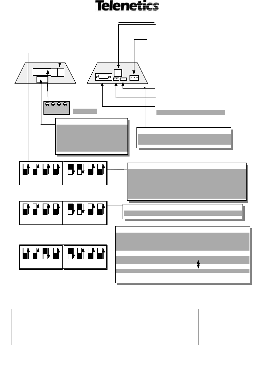
Point-to-Point, 4-Wire: Set Switches B-3 & B-4 DOWN(OFF)
Point-to-Point, 2-Wire: Set Switches B-3 & B-4 UP(ON)
Line Terminate DC : Set Switches B-1 & B-2 UP(ON)
Line Terminate AC : set Switches B-2 UP(ON)
For LoopBack Test mode : Set Switches B-3 & B-4 UP(ON)
Multi-drop (Host), 4-Wire: Set Switches B-3 & B-4 DOWN
Multi-drop (Host), 2-Wire: Set Switches B-3 & B-4 UP
Multi-drop (Slave), 4-Wire: Set Switches B-3 & B-4 DOWN
Multi-drop (Slave), 2-Wire: Set Switches B-3 & B-4 UP
Line Terminate : Set Switches B-2 & B-1DOWN (OFF) for
all Slaves except UP(ON) on unit furthest
Switch A-1: RTS/CTS Delay: UP = 0 sec; DOWN = 7ms
Switch A-2: DOWN = TXD enables TX +5ms Select only A-2 or
Switch A-3: DOWN = RTS enables TX A-3
Switch A-4: UP(ON) = TX clamps RXD off (ON) in 2-Wire (half duplex) mode
4 3 2 1
Earth/Digital Ground (Jump pins if req’d) *
♦ Steady = MODEM CONNECTED (CD)
RS232 Data Port (DB9 female)
for modem configuration only.
TX+ TX- RX+ RX-
(* Not on MIU232/485 Converter)
1 UP, 2 DOWN when using DB9
connected to RS485. Do not
MIUXXX/485 DIP SWITCH SETUP


