18
MZ-RH910
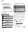
6. Set the laser power meter so that the laser beam from the optical
pick-up aims at the objective lens of laser power meter at right
angle. (Confirm it with the disc not inserted)
7. Confirm that the value of laser power meter is 0.860 mW ±
19.2%.
8. Press the > key to select the item number 9112.
9. Confirm that the value of laser power meter is 0.763 mW ±
18.2%.
10. Press the > key to select the item number 9113.
11. Confirm that the value of laser power meter is 6.87 mW ±
12%.
12. Press the x key four times and back to the Display Check
mode.
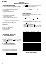
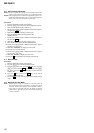
3-5. Setting The Adjustment Values
3-5-1. Hi-MD3 setting
Preparation:
1. Perform calculation every item based on the data given by the
Hi-MD3 adjustment disc by referring to the following table.
(Round off the value in decimal place)
2. Convert the calculated value into hexadecimal number.
Note: The Hi-MD3 adjustment parameters vary depending on the disc,
and therefore use the parameters of the disc used when performing
the adjustment.
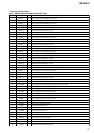
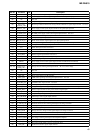
Item No. Calculating formula (*3)
0211 Pr_nominal / 0.05
(*1) Por / 0.05
0212 Kr × (−100)
0213 Pw_nominal / 0.05
(*2) Ppw / 0.05
0214 Kw × (−100)
0215 Prmin / 0.05
0216 Pwmin / 0.05
*1) If the “Pr_nominal” value is indicated, use the “Pr_nominal” value
and not used “Por” value.
*2) If the “Pw_nominal” value is indicated, use the “Pw_nominal” value
and not used “Ppw” value.
*3) Round off after the decimal point.
Table 3-5-1. Hi-MD3 adjustment parameter
7. Adjust with [VOL+]/[VOL--] keys so that the value of digital
multi meter becomes 1.80 ± 0.01V.
8. Press the X key on the set or – key on the remote
commander to write the adjusted value.
9. Press the > key to select the item number 2262.
10. Confirm that the value of digital multi meter is 1.20 ± 0.024V.
11. Press the > key to select the item number 2263.
12. Confirm that the value of digital multi meter is 2.17 ± 0.05V.
13. Press the x key four times and back to the Display Check
mode.
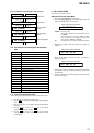
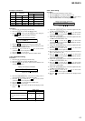
3-3-2. Ampere checks
Procedure:
1. Connect the 22 ohms resistor (more than 0.1 watts) and ampere
meter to battery terminals.
2. Connect the AC adapter to the set.
3. Enter the test mode (Display Check mode).
4. Press the [VOL+] key to enter the Manual mode.
5. Press the [VOL+] key twice, press the > key once, press the
[VOL+] key once, press the > key once, press the [VOL+]
key three times, press the > key four times to select the
item number 2264.
6. Confirm that the value of ampere meter becomes specification
value. (Refer to “table 3-3-1. Ampere Specifications”)
7. Press the x key four times and back to the Display Check
mode.
8. Cut the power supply and remove the resistor that connected
to the battery terminals.
9. Repeat checks to item number 2267 at the same manner as
step 1 to step 8. ( Refer to “table 3-3-1. Ampere Specifications”
for the kind of the resistor that connected to the battery
terminals at step 1)
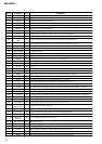
ItemNo. Display Specification value Connected Resistor
2264 20mA I ** 20 mA ± 11 mA 22Ω (more than 0.1W)
2265 140mAI ** 140 mA ± 14 mA 10Ω (more than 1.0W)
2266 170mAI ** 170 mA ± 15 mA 10Ω (more than 1.0W)
2267 500mAI ** 500 mA ± 32 mA 2.2Ω (more than 1.5W)
Table 3-3-1. Ampere Specifications
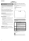
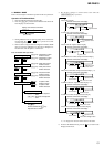
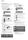
6. Press the > key to select the item number 2261 and display
as follows.
Display of the remote commander
3-3. Charge Function Check
Note1: When perform this check, don’t apply a voltage to battery terminals.
Note2: Be sure to disconnect the AC adapter when connecting the resistors.
Doing so with the power supply connected causes a trouble.
3-3-1. Voltage adjustment and checks
Procedure:
1. Connect the digital multi meter to battery terminals.
2. Connect the AC adapter to the set.
3. Enter the test mode (Display Check mode).
4. Press the [VOL+] key to enter the Manual mode.
5. Press the [VOL+] key twice, press the > key once, press the
[VOL+] key once, press the > key once, press the [VOL+]
key three times to display as follows.
Display of the remote commander
3-4. Laser Power Check
Procedure:
1. Enter the test mode (Display Check mode).
2. Press the [VOL+] key to enter the Manual mode.
3. Open the lid and press the . key continuously until the
optical pick-up moves to the most inward track.
4. Press the [VOL--] key once to display as follows.
Display of the remote commander
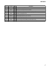
260 ChrgNi
009 DESIGN
111 LrefPw **
5. Press the > key three times to select the item number 9111
and display as follows.
Display of the remote commander
adjustment value (hexadecimal)
261 ChgAdj **