22
MZ-N10
Power Supply Adjustment Auto Item Feed
Note :This mode is available to perform the temperature correc-
tion and power supply adjustment without entering the
manual mode.
• Setting method of power supply adjustment auto item
feed mode.
1. Set the test mode (see page 11)
2. Press the . or [VOL --] key to activate the overall adjust-
ment mode.
3. Turn the jog dial (up), or press the [P MODE] key on the
remote commander to set the temperature correction mode.
4. To change the initial value (hexadecimal), adjust with the [VOL
+] or [VOL --] key.
Press the X key to write the adjusted value, and the item
number increases automatically.
When not writing the adjusted value, press the > key to
move to the next item.
.
key
>
key
.
key
>
key
.
key
>
key
.
key
>
key
.
key
>
key
The jog dial (up) or
P MODE
key on the remote
commander
000Assy **
015 SetTmp 19
741 VC1 L **
742 VC1 H **
743 VC2 Lo **
744 VC2 Hi **
745 REG1 **
.
key
>
key
>
key
>
key
>
key
.
key
>
key
.
key
>
key
751 VREC L **
752 VREC M **
753 VREC H **
754 3.3upc **
.
key
>
key
755 ChgV L **
.
key
>
key
756 ChgV H **
.
key
>
key
757 CIL **
>
key
000 ADJ OK
.
key
.
key
>
key
746 REG2 **
747 REG3L1 **
>
key
.
key
748 REG3L2 **
749 REG3 H **
.
key
.
key
5. Connect a digital voltmeter to the test points on the MAIN
board, and adjust the voltage with the [VOL +] or [VOL --]
key. (see page 18 to 20)
Press the X key to write the adjusted value, and the item
number increases automatically.
6. When not writing the adjusted value, press the > key to
move to the next item.
The . key is available to back to the last item.
7. The following message is displayed after all power supply ad-
justments finish.
8. Press the x key to return to the test mode (display check
mode).
Remote commander LCD display
Assy**
000
Remote commander LCD display
**
: Adjusted value
SetTmp
@
**
015
Remote commander LCD display
**
: Adjusted value
VC1 L **
741
Remote commander LCD display
ADJ OK
000
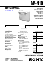
Configuration of power supply adjustment auto item feed