ST4125G/ST6125G SUBMERSIBLE PUMP• OPERATION MANUAL — REV. #0 (11/18/10) — PAGE 13
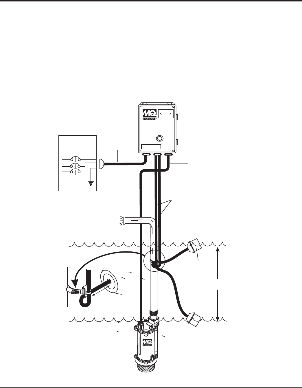
Float Switches
For unattended operation of the submersible pump two
single fl oat switches (Model SW-1WOPA) will be required.
These fl oat switches can be connected directly to a control
box (bare wires) and will allow the pump to turn on and off
depending on the length of the tether.
FLOAT SWITCHES
Figure 6. Float Switch Application
Mounting The Float Switches
1. Determine the required cord tether length as shown
in Figure 3 and Table 2.
2. Place the cord into the clamp as shown in Figure 6.
3. Secure the clamp to the discharge hose as shown in
Figure 6. DO NOT install cord under hose clamp.
4. Using a screwdriver, tighten the hose clamp. DO NOT
over- tighten. Make sure the fl oat cord is not allowed
to touch the excess hose clamp band during operation.
PUMPING
RANGE
MODEL SW-1WOPA
FLOAT SWITCH (2)
3.5 in. (9 cm.)
MINIMUM
TETHER
LENGTH
PUMP
ON
PUMP
OFF
DISCHARGE
HOSE
INPUT POWER
TO CONTROL BOX
FLOAT SWITCH
CABLES (2)
SUBMERSIBLE
PUMP
CONTROL
BOX
CAUTION!
HIGH
VOLTAGE!
CB12/14
RESET
PUMP POWER
CABLE
EXTERNAL 3-PHASE
(230 OR 460 VOLT)
POWER SOURCE
CIRCUIT
BREAKER
RED
WHITE
BLACK
L1
L2
L3
GREEN
GND.
