4. Reinstall the control panel and tighten the 2 retaining
screws.
5. On the top of the unit, to the right of the control box
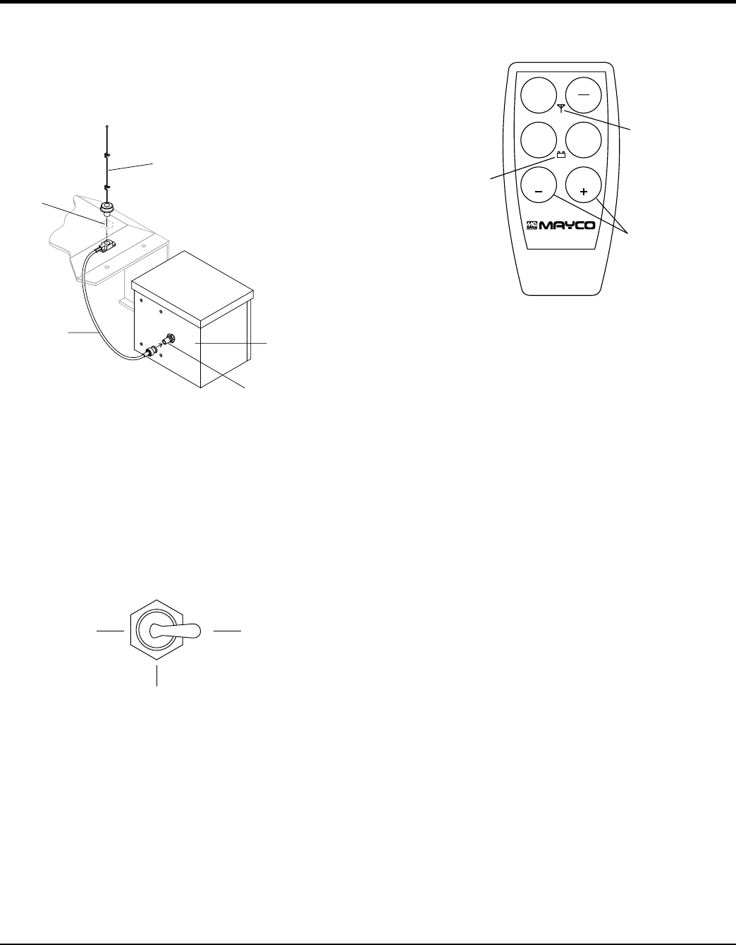
(Figure 37), hammer out the knock-out hole and install
the remote antenna.
Figure 37. Antenna Installation
6. Connect the antenna cable to the connector on the
rear (Figure 37) of the control box.
Radio Remote Control Buttons Operation
Before the remote control hand-held module can be used,
the pumping control switch on the control box must be
placed in the REMOTE position ()Figure 38.
Figure 38. Pumping Control Switch (Remote)
ANTENNA
KNOCK-OUT
HOLE
ANTENNA
CONNECTOR
CABLE
CONTROLBOX
CONNECTOR
REAR OF
CONTROLB
LOCAL
CENTER
OFF
Remote pumping operation can be performed by the hand-
held radio remote control (Figure 39).
Figure 39. Radio Remote Control
The buttons on the hand-held remote control module have
the following functions:
ON/OFF – Turns the power on or off. When power is on
the power LED lights red. If the battery LED turns red,
9V battery needs to be replaced.
E-STOP – Turns off the pump completely in an
emergency.
– Starts and stops the forward pumping.
– momentarily pumps in reverse direction.
– used to increase the pumping volume.
– used to decrease the pumping volume.
E-STOP
ON
OFF
PUMP
REV
VOLUME VOLUME
PUMP
ON/OFF
POWER
NOTE:OLDERMODELS
MAYINDICATE
INSTEADOF
FLOW
VOLUME
TTERY LED
OPERATION
