HBC19A/HBC25A REBAR CUTTER • OPERATION AND PARTS MANUAL — REV. #4 (03/30/09) — PAGE 9
COMPONENTS
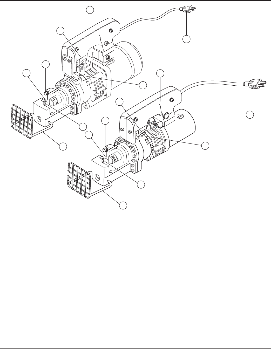
Figure 1. HBC19A/HBC25A Components
Figure 1 shows the components of the HBC19A/HBC25A
Rebar Cutter. These components are described below.
1. Blade (set of two) - Cuts the rebar that is set on the
holder between the blades.
2. Spacing Bolt and Nut - Allows rebar of different
diameters to be cut by adjusting the space between
the blades.
3. Rebar Holder - Holds the rebar to be cut.
4. Protector - Covers the rebar while cutting to prevent
rebar fragments from flying out.
5. ON/OFF Switch - Starts the cutting of the rebar when
the trigger switch is squeezed. When released, cutting
is stopped. Do not release release switch until the rebar
is completely cut.
6. Handle - Used to lift the rebar cutter.
7. Return Valve - Returns the cutter rod to the starting
position when the cutter blade jams and stops the
cutting of a rebar. This is done by rotating the return
valve half a turn in a counterclockwise direction with
the hexagonal wrench supplied with the unit.
8. Power Plug - connects to a 150 V, 60 Hz power source.
HBC19A
HBC25A
1
1
4
4
2
2
3
3
5
5
7
7
8
8
6
6
