Counter module
05/02 AWB2725-1452GB
22
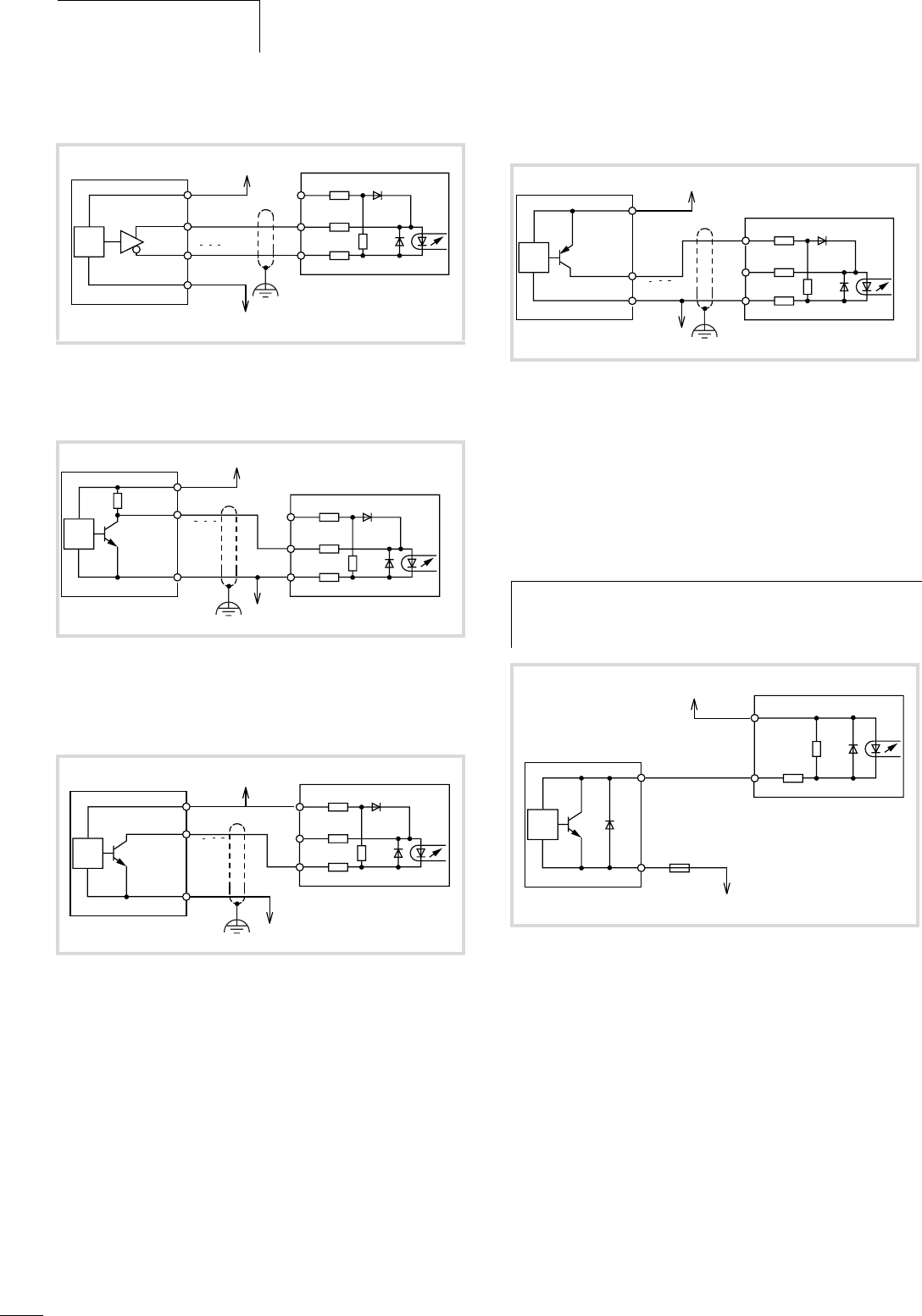
Incremental encoder with differential output
Incremental encoder with NPN transistor output
Incremental encoder with NPN transistor output
(open-collector)
Incremental encoder with PNP transistor output
(open-collector)
Connecting third-party equipment to the
comparator output
The counter module has 2 open-collector transistor outputs per
channel. The diagram shows how third-party equipment should be
connected to the counter module.
Figure 23: Connection for an incremental encoder with a differential
output (example)
Figure 24: Connection for an incremental encoder with an NPN tran-
sistor output (example)
Figure 25: Connection for an incremental encoder with an open-
collector NPN transistor output (example)
(–)
12 – 24 V H
XIOC-2(1)CNT
V
IN
(+)
+ V
A, B, Z
A, B, Z
0 V
0 V
Incremental encoder output
12 – 24 V H
XIOC-2(1)CNT
V
IN
(+)
+ V
A, B, Z
Z A, B, Z
0 V
0 V
(–)
V
IN
12 – 24 V H
XIOC-2(1)CNT
(+)
(–)
+ V
A, B, Z
0 V
0 V
Z A, B, Z
Incremental encoder output
Figure 26: Connection for an incremental encoder with an open-
collector PNP transistor output (example)
h
Important!
Wire in a fuse (0.5 A) as shown in the diagram, to protect
the internal circuitry
Figure 27: Connecting third-party equipment to the counter module
12 – 24 V H
XIOC-2(1)CNT
V
IN
(+)
+ V
A, B, Z
0 V
0 V
(–)
Z A, B, Z
Incremental encoder output
12 – 24 V H
0.5 A
0 V
F 20 mA
XIOC-2(1)CNT
Third-party equipment


