- 14 -
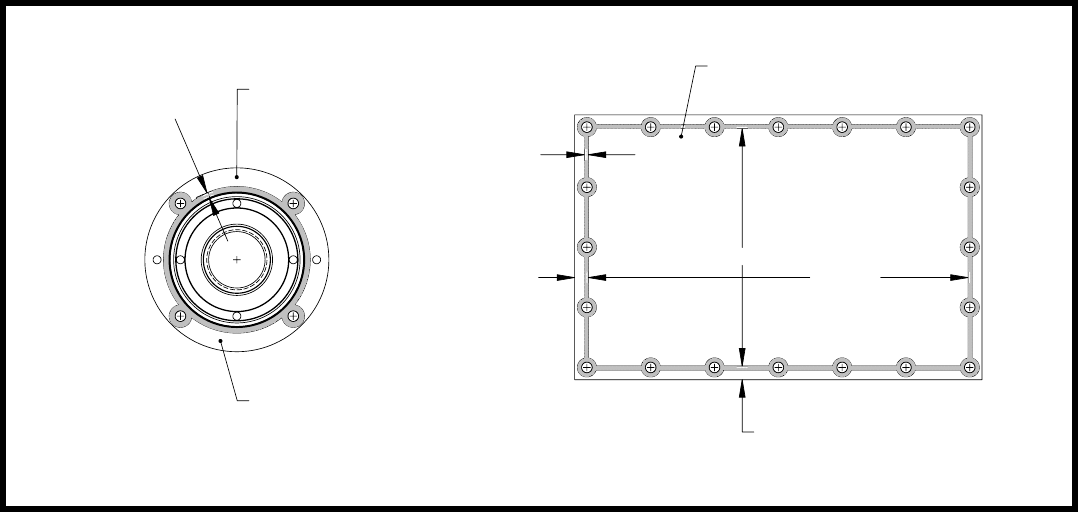
%($'
/2&7,7(
*$6.(70$.(5
+286,1*6,'(
2)&29(5
6+$)7%($5,1*
&29(5
%$6(3/$7(&29(56($/$17$33/,&$7,21
%($'
/2&7,7(
*$6.(70$.(5
0$,1+286,1*
&29(5
),*85(),*85(
6. Remove the external snap ring (#6) from the pinion
shaft (#24).
7. Slide the pinion shaft (#24) out of the control
housing(#13). Note the size and location of the
O-rings (#4 ) for assembly.
8. Remove the O-rings (#4 & #5) from the pinion shaft
(#24).
9. Slide the rack gear (#15), seal (#2) and guide ring
(#3) out of the control head housing. Note the
orientation of the seal lip.
10. Remove the hex head cap screw (#26) and washer
(#31) from the rack gear (#15).
11. Remove the hydraulic seal (#2) from the rack gear.
Be careful to prevent scratching the seal
mounting area of the rack gear.
12. Use a 1/4” pin punch to drive the slide bushing (#14)
out of the control head housing.
Baseplate Assembly Procedure
Refer to BASEPLATE ASSEMBLY, page 24.
1. Clean all baseplate components.
2. Note: Make sure the bearings and their inner
races are kept as a matched set.
3. Inspect all bearings, shafts, helix pin carrier and
gears for wear, debris and discoloration from heat.
Replace as needed. Replace the roller bearings
and the inner races on each shaft as a set (both
bearings on the shaft) as needed. Replace the
helix carrier ball bearings as a set at each
complete disassembly or rebuild. Replace all
seals and gaskets removed at each disassembly
or inspection.
4. Install the input shaft cover seal (#5) into cover (#9).
5. Press the roller bearings (#4) into all four of the
covers (#7, #9, #12 & #18). Note: Make sure the
bearings and their inner races are kept as a
matched set.
6. Install the hex head flange screws (#21) into the shaft
bearing covers using LOCTITE #243 thread locker
sealant.
7. Install the plastic plugs (#1) in the threaded holes
used to press the covers out of the baseplate.
8. Install the key (#12) into the idler shaft (#8).
9. Align the idler gear (#11) with the key (#12) and idler
shaft (#8) and press the idler gear onto the idler shaft
using exciter oil as a lubricant. Reference the figure
5 for the idler gear and shaft orientation.
10. Press the bearing inner races onto the idler shaft/
gear assembly. The flanged end of the inner race
goes toward the shoulder on the shaft.
11. Place the idler shaft and gear assembly into the
baseplate housing in the forward location. Note: The
housing is not symmetric. The input/pulley side
of the housing has a pocket machined for the belt
bellows. This pocket is to be oriented toward the
front left side of the machine. The end of the idler
shaft with the hole goes toward the front right
side of the machine with the breather/cover (#18).
12. Install the idler shaft covers (#7 on the pulley side,
and (#18 on the hydraulic side). Secure each cover
with four hex head flange screws (#23) using
LOCTITE #243 on the bolt threads and torque the
flange screws to 13 ft.-lbs. See the figure #3 for
LOCTITE #515 gasket maker application. Check
idler shaft for minimum of .020” end play after
covers are installed and the bolts are torqued.


