SECTION 6—OPERATING INSTRUCTIONS
Part No 1156872 27 Invacare SOLO
2
™
LCD Displays
NOTE:Forthisprocedure,refertoFIGURE6.9onpage 30.
Therearefourdifferent“Display”screensandtwo“A dj u st m en t ”screens
av ailablethroughtheLCDdisplaythat , alongwith theWarningandAlarm
screens,providefullcontrolandinformationtotheuser.
Standby Screen
WhentheexternalACpowersupplyisattachedandproviding
power,the
unitwillshowtheStandbyscreen.
WhentheunitisoffandeithertheBatteryortheDCPowerarepresent,a
momentarypushoftheOn/Offbuttonwilldisplaythisscreenbriefl y.
Thisscreenisperiodical lydisplayedduringnormaloperation.
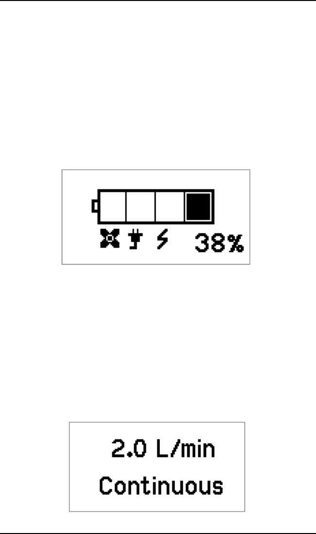
FIGURE 6.5 Standby Screen
TheStandbyscreenprovidesbothabattery
gaugeandapercentageof
remainingcharge.ItcanalsodisplaytheFansOperating,ExternalPower
OnandBatteryChargingiconswhenapplicable.
Normal Operating Screen
Whenoperatingnormally,theMode &Flowdisplayinformstheuserofthe
currentoperatingmodeandthesettingforthatmode.
Thedisplayshows thecurrent/lastmo de
ofoperationselected.Themodeof
operationcanbe eitherContinuousFloworPulseDose.Itwill alsoshowthe
current/lastoutputflowlev elselected.
ThisscreenwillalternatewiththeSt andbyscreenevery20seconds.Inthis
fashiontheuserwillbeabletoseealltheimportant informationat
aglance.
FIGURE 6.6 Normal Operating Screen


