7
ASSEMBLY
NOTE: You may now roll or drive your tractor off the skid.
Follow the appropriate instruction below to remove the
tractor from the skid.
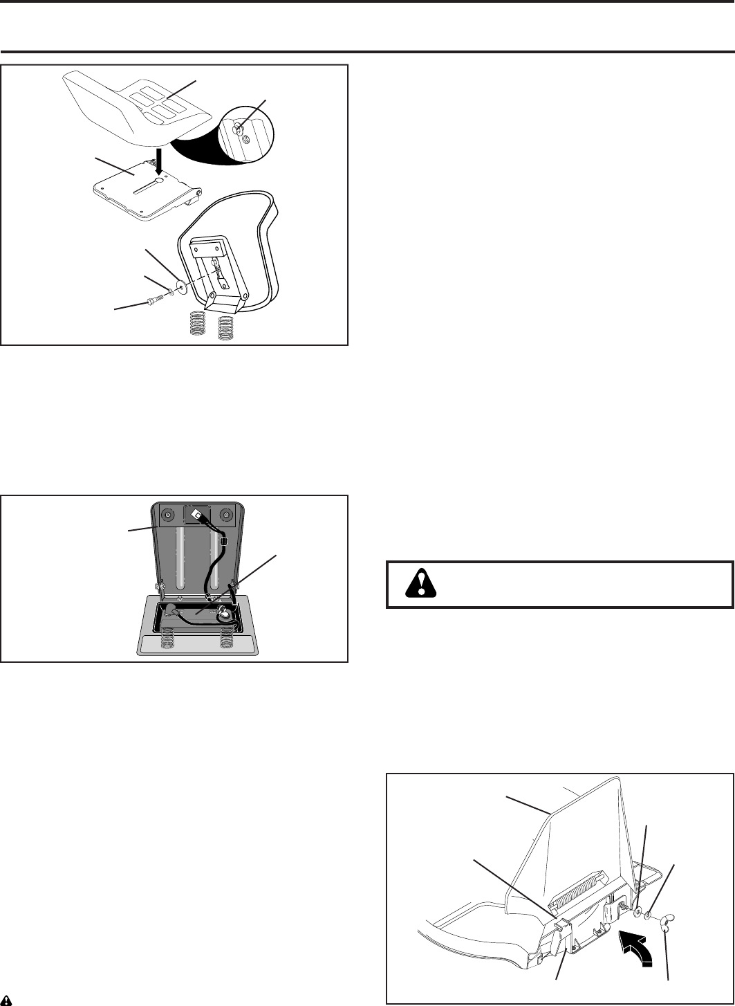
FIG. 2
SEAT PAN
SHOUL-
DER BOLT
SEAT
ADJUSTMENT
BOLT
LOCK WASHER
FLAT WASHER
TO ROLL TRACTOR OFF SKID (See
Op er a tion section for location and function
of con trols)
• Press lift lever plunger and raise attachment lift lever
to its highest po si tion.
• Release parking brake by depressing clutch/brake
ped al.
• Place gearshift lever in neutral (N) po si tion.
• Roll tractor forward off skid.
• Remove banding holding defl ector shield up against
trac tor.
TO DRIVE TRACTOR OFF SKID (See Op-
er a tion section for location and func tion of
con trols)
WARNING: Before starting, read, un der stand and follow
all in struc tions in the Operation section of this manual.
SEAT PAN
LABEL
FIG. 3
CHECK BATTERY (See Fig. 3)
• Lift seat pan to raised position.
• If this battery is put into service after month and year
indicated on label (label located between terminals)
charge battery for minimum of one hour at 6-10 amps.
(See “BATTERY” in the Maintenance sec tion of this
manual for charg ing instructions).
Be sure tractor is in a well-ventilated area. Be sure the area
in front of tractor is clear of other people and objects.
• Be sure all the above assembly steps have been com-
pleted.
• Check engine oil level and fi ll fuel tank with gasoline.
• Sit on seat in operating position, depress clutch/brake
pedal and set the parking brake.
• Place gear shift lever in neutral (N) position.
• Press lift lever plunger and raise attachment lift lever
to its highest position.
• Start the engine. After engine has started, move throttle
control to idle position.
• Depress clutch/brake pedal into full "BRAKE" position
and hold. Move gearshift lever to 1st gear.
• Slowly release clutch/brake pedal and slowly drive
tractor off skid.
• Apply brake to stop tractor, set parking brake and place
gearshift lever in neutral position.
• Turn ignition key to "OFF" position.
Continue with the instructions that follow.
WING NUT
MULCHER PLATE
FLAT
WASHER
DEFLECTOR
SHIELD
HANG
TAB
LOCK
WASHER
FIG. 4
INSTALL MULCHER PLATE (See Figs. 4)
(If Previously Removed)
• Raise and hold defl ector shield in the upright posi-
tion.
• Position alignment cup over rear baffl e.
• Pivot mulcher plate forward and hook on mount ing bolt.
Be sure hang tab hooks top of deck opening.
• Assemble fl at washer, lock washer and wing nut to
mount ing bolt and tighten securely.
CAUTION: Do not remove defl ector
shield from mow er.
TO CONVERT TO BAGGING OR
DISCHARGING
Simply remove mulcher plate and store in a safe place.
Your mower is now ready for discharging or installation of
optional grass catcher accessory.
NOTE: If discharging or bagging results are unsatisfactory
with mulcher blades on mower, remove the mulcher blades
and install high performance discharging blades, which are
available at an authorized service center/department.


