P/N 480-0005-00-15 2-23
Chapter 2: Hardware Components
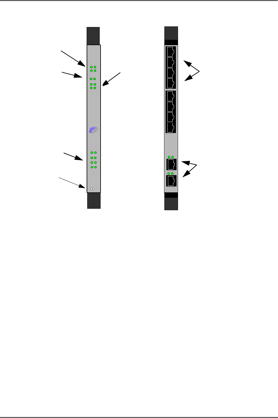
Figure 2-20 DS1 Card
Status LEDs
• Alarm. Red light indicates a major software alarm has been reported for the card. A green light indicates
no alarms have been reported. See Chapter 7: System Alarms for more information.
• Status. Indicates overall health of the card. Red (or amber) light indicates minor problems were found
with the system but the card can be removed without intervention. A green light indicates no problems
were found.
• CPU. Green light indicates the CPU bus is active.
• PCI. Green light indicates the local PCI bus is busy.
DSP LEDs. LEDs provide a high level indication of the DSP card activity. See Chapter 8: Diagnostics/Main-
tenance for a detailed description for troubleshooting purposes.
• DSP Bank 1: Lights for DSP module activity on the first DSP module.
• DSP Bank 2: Lights for DSP module activity on the second DSP module.
For both DSP banks, red indicates power-up or DSP module is usable; green indicates at least one DSP chan-
nel is in use. Unlit indicates the DSP is not in use.
Ethernet LEDs. Not available in current release.
Status LEDs
DSP LEDs
Ethernet LEDs
N/A
Span Status LEDs
RJ-48 Input/Output ports
for T1/E1 connection
Ethernet Ports/Ethernet LEDs
N/A
Front View
Rear View
TM
Hot Swap
DS1
StatusAlar m
12
PCICPU
BankDSP
1
2
TX/RXLink
1
2
3
4
5
6
7
8
10/100
Ethernet
Span
Status
TECHNOLOGIES,
INC.
Q
UINTUM
TM
1
2
3
4
DS1
1
2
3
4
10/100
Ethernet
Link TX/RX
Link TX/RX
Hot Swap LED


