M:\Product Information\366-348\Instructions\366-348 MGB Fuel Injection Installation Instructions_Grant_2.doc
Part 19, continued
366-348 Inst Fig 166
166.1
166.2
166.3
222. Slide small hose clamps over each end of the 24”
length of 5/16” fuel hose.
223. Remove the original hose from the steel fuel line
over the rear axle.
224. Connect one end of the 24” piece of hose to the
original steel fuel line. Tighten the clamp. If you found
rust flakes in the gas you drained from the tank, we
strongly suggest the addition of a second in-line fuel filter
in the hose between the tank and the pump.`
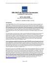
225. Hold the fuel pump so the end with the electrical
connections is “up” (166.1)
226. Slide the loose end of the 24” long piece of hose
(166.2) onto the fitting on the end of the pump.
227. Tighten the hose clamp (166.3). This hose will now
serve to suspend the pump while we make the rest of
our connections.
228. Slide a small hose clamp over each end of the 36”
length of 5/16” fuel hose.
366-348 Inst Fig 170 77-80 MGB
170.1
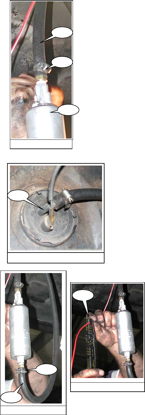
229. Locate the fuel sending unit on the right side of the
fuel tank. Remove the old hose from the fitting on the
tank (170.1). Slide one end of the 36” piece of fuel hose
onto the fitting on the gas tank. Tighten the clamp. On
the 74.5-76 MGBs, there is a rigid steel line running from
the sending unit to a hose that is connected to the pump.
The steel line should be removed and cut with a tubing
cutter at a convenient point. Reconnect the line to the
sender. Slide the hose onto the cut end of the line and
secure it with a clamp.
366-348 Inst Fig 172
172.1
172.2
366-348 Inst Fig 174
174.1
230. Connect the loose end of the 36” hose (172.1) to the
open fitting on the fuel pump. (This end of the pump
does not have the electrical connections) Tighten the
hose clamp (172.2).
231. Let the red wire with white stripe hang down past the
pump. Pinch the wire where it reaches the middle of the
pump and cut the wire. (174.1)
Page 34 of 52