52
Chapter 7: Troubleshooting
Problem:
'Board not found' message appears on the screen when running test
software.
Solution:
Another I/O card might be using the same base address location as the PC
62C. Try a different base address other than the manufacturer’s default
base address (eg: 700h) and re-run test software 62CTEST.EXE found in
sub directory C:\EDR\TPAS\DEMOS\. If the problem persists then try
increasing the wait states on the PC 62C. If the PC 62C still does not work
even after the maximum number of wait states was chosen then try a
different computer with a different motherboard. If the test still fails then
the PC 62C is faulty. Return the board to your distributor for repairs.
Problem:
Data written to the digital Output Register does not set the output ports
correctly.
Solution:
Check the ports using the walkbit test program called WALKBIT.EXE
found in EDR\TPAS\DEMOS subdirectory. Monitor the digital lines of on
connector J6 and check if the problem persists. If so, then the Digital
Output Latches might be faulty. Please send the PC 62C back to your
distributor for repairs.
Problem:
I connected a push button to one of the input port lines. When it is closed
it is set to +5V (yield a logical 1) and the program reads a logical 1.
However, when it is open, random numbers are read by the program on the
digital input lines.
Solution:
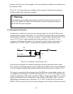
When the push button is not connected, the port line is in a floating (not
connected). You must connect a ‘pulldown’ resistor (experiment from
330R to 1k) to the port line in order to ensure that it is in a defined state.
Also note that if a port is configured as an input then all unused lines
MUST be grounded. See Section 6.2 for more details.
Problem:
Interrupts does not occur when any of Opto-Isolators receives a pulse from
0V to above the threshold of 3.1V. In other words, a square pulse Posituve
edged 0 to 24V does not yield an interrupt.
Solution:
It is possible that the Opto-isolator was not configured in Interrupt Mode.
First read back the IGATE Register [Base + 6] and check if the
appropriate Interrupt Enable Bit was set. For example, if an IRQ does not
occur on Opto isolator 0, check if bit 0 was enabled. If not, set it to 1.
Next, configure the IRQ to any of 8 using the IMUXP0 Register (Bits 0 to
2). Re-trigger the Opto-isolator. An IRQ should occur.