13
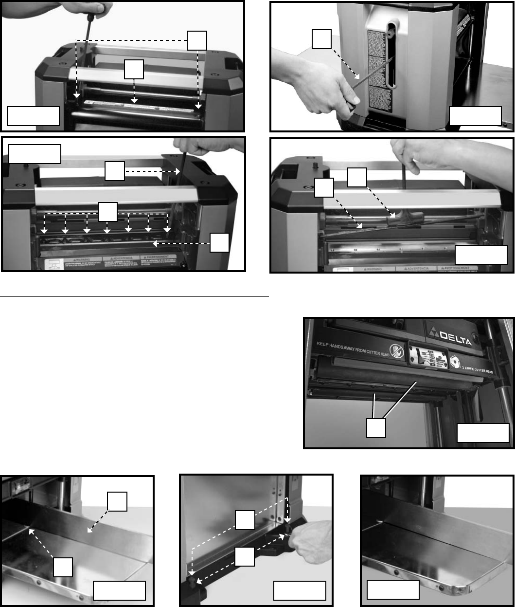
8. Take this time also to clean the rollers (I) Fig. 22A.
9. Your unit is equipped with double-edged knives. If the second edge of the knife has not been used, rotate the
knife 180 degrees and replace on the cutterhead. Replace the knives if both sides have been used.
10. Attach the hold-down bar (F) Fig. 21 that you removed in STEP 4. Tighten all fasteners securely.
11. Depress the cutterhead lock release and rotate the cutterhead to the next empty position until the cutterhead lock
engages.
12. Repeat steps 9 through 11 to replace the other knives.
13. Reattach the cutterhead guard or dust collection attachment.
A
Fig. 19
Fig. 20
Fig. 21
Fig. 22
C
E
F
G
H
HOW TO ADJUST THE INFEED AND OUTFEED TABLES
Your unit has been factory set to eliminate snipe. If your unit loses
its adjustment and causes snipe, you can adjust the infeed and
outfeed tables to minimize this condition.
1. Place a dime (A) Fig. 23A at each end of the platen (infeed and
outfeed).
2. Place a straight edge (B) across the two dimes. Extend the
straight edge past the leading edge of the infeed and trailing
edge of the outfeed tables.
3. If your tables are properly adjusted, the straight edge will touch
both of the dimes and the edges of the tables (Fig. 23C).
4. If your table needs adjustment, loosen the locknuts (A) Fig. 23B
on the table height-adjustment screws (B). Adjust the screws
up or down to achieve the desired table height.
5. Make sure that both height-adjustment screws contact the
bottom of the table after adjustment.
A
B
A
B
Fig. 23A Fig. 23B
Fig. 23C
Fig. 22A
I
B
D
