11
- Typical setups are shown below with the pressure relief
valve attached. The pressure relief valve is supplied with
the heater, and should only be fitted on the hot water
outlet as shown. The cold water inlet setup will be
identical to diagrams below but without the pressure relief
valve.
- For ease of installation the piping setup should be
prepared as one whole piece with either threaded or
sweated connections. The entire assembly will then
mount easily against a wall and to the back of the
Aquastar.
THREADED ASSEMBLY
Connecting the pressure relief valve (PRV)
The listed pressure relief valve supplied with the heater must
be installed at the time of installation. Should a discharge
line be added to the PRV no valve is to be placed between
the PRV and the heater. No reducing coupling or other
restriction may be installed in the discharge line. The
discharge line must be installed such that it allows
complete drainage of both the PRV and the line. The location
of the PRV must be readily accessible for servicing or
replacement. and be mounted as close to the water heater
as possible. To install the PRV, a suitable fitting connected
to an extension on a “T” fitting can be sweated to the hot
water line. See Fig 9.
Fig. 8 - Plumbing connections for the Aquastar 125FX
SWEATED ASSEMBLY
HWSHWS
CWSCWS
Pressure
Relief
Valve
Pressure
Relief
Valve
Fig. 9 - Pressure Relief Valve
ELECTRICAL CONNECTIONS
WARNING: This heater must be electrically grounded in accordance with the most recent edition of the National
Electrical Code, NFPA 70. In Canada, all electrical wiring to the heater should be in accordance with local codes and the
Canadian Electrical Code, CSA C22.1 Part 1. Do not rely on the gas or water piping to ground the metal parts of the
heater.
CAUTION: Label all wires prior to disconnection when servicing controls. Wiring error can cause improper and dangerous
operation. Verify proper operation after servicing.
The AquaStar 125FX requires an electrical power supply from 120VAC 60Hz circuit and must be properly grounded.
- A means for switching off the 120 VAC power supply must be provided.
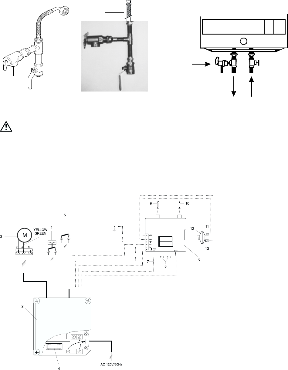
- The heater is wired as shown in the wiring diagram. (Fig 10).
Fig 10: Wiring Diagram for AQ 125FX
9 - ionization probe (flame
sensor)
10 - pilot electrode
11 - pilot electrovalve
12 -
Diaphragm switch
13 - burner electrovalve
14 - power cord
1 - microswitch
2 - electric control box
3 - exhaust fan
4 - fuse
5 - circuit interrupter
6 - electronic control box
7 - temperature limiter
8 - sensors of exhaust gases
E864_020
PIPE PRV TO
APPROPRIATE
DISCHARGE
1/2” FLEX
PIPE PRV TO
APPROPRIATE
DISCHARGE
1/2” FLEX


