Page 10
724-746-5500 | blackbox.com
Chapter 3: Setup and Installation
3. Setup and Installation
3.1 Cabling Considerations
We recommend mounting and connecting all cabling to the Multi DVI System
components before applying power. Note the recommended power sequence
below.
3.2 Making the Connections
3.2.1 Connections and Setup in General
This section contains figures showing connections with the specific Multi DVI
System models. In general, however, the connection and setup procedure at both
transmitter and receiver ends is as follows:
At the transmitter end:
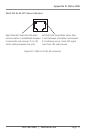
1. Connect the source video to the Multi DVI System transmitter video input port,
which is a DVI connector labeled DVI IN.
2. If desired, attach a local monitor via the local monitor port to DVI OUT.
3. Connect the CAT5/5e/6 cable to the transmitter.
4. Do not power on the transmitter at this time.
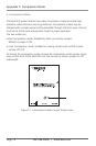
At the receiver end:
1. Connect the DVI OUT connector to the display unit,.
2. Make sure that the CAT5/5e/6 cable connections from the transmitter or
receiver are secure.
3. Power on the display, then the receiver.
4. Next, the transmitter should be powered on and finally the source video signal.
Reference Appendix B for Link status and LED indicator explanations.
If there are any problems at either end, see Chapter 4.
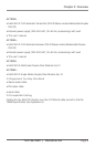
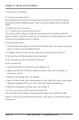
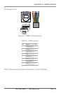
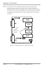
3.2.2 Connections on the Single-Port Multi DVI
The AC1100A and AC1102A units support DVI video over CAT5/5e/6 cable.
Figure 3-1 shows the transmitter connections, and Figure 3-2 shows the receiver
connections.