


CPS2000 Fan Control & PCB SC4032
Technical Description
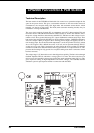
The later models of the CPS2000 are fitted with a fan control servo system that adapts the fan
speed to the power drawn. This gives a substantial reduction in fan noise under almost all
circumstances; the exception being 10% high mains and maximum current drawn, which
naturally sets the fan to full speed. The PCB (with associated mounting bracket) may be
retrofitted to existing CPS2000 units.
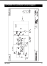
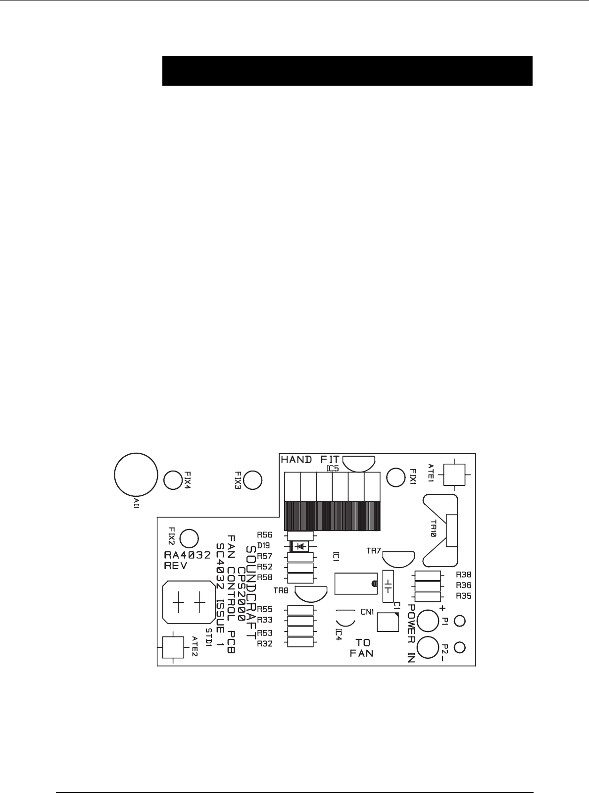
The servo circuit consists of opamp IC1-A, temperature sensor IC5, shunt regulator IC4, and
fan control devices TR7,TR10. IC4 maintains 2.50V between its "anode" and "cathode"; this is
the precise voltage that drives the reference chain R53,55. TR8 also uses this voltage to set its
emitter at 4.4V above ground; this keeps IC1’s inputs within their common-mode range. Thus
both ends of the voltage divider R53-R55 are fixed at defined voltages. LM35DZ temperature
sensor IC5 outputs 10mV per degreeC above freezing point (0 degC) and applies it to IC1-A
non-inverting input. The desired heatsink temperature is set at the junction of R53,55, which
sits at +5.0V approx. This is 600mV above the +4.4V rail, and so represents 60 degC. R52,57
set the servo loop gain. This is designed to be safely below the level at which slow thermal
oscillations would occur. R56,D19 increase the loop gain when IC1-A output is below 4V. This
prevents the fan sitting for long periods in a not-quite-running state where it consumes current
but does not rotate.
The voltage range 1-4V where this occurs is thus skipped over quickly. The fan is driven through
feedback amplifier TR7,10, which has a voltage gain of 1.3 times. This allows the fan to be
driven over its full operating voltage range despite the output saturation limits of IC1-A. This
gives improved cooling at high temperatures and mains voltages. The CPS2000 thermal
shutdown system is quite separate and has no connection with this PCB.
36 Fan Control