


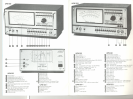
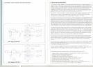

UPM 550-1
The version UPM 550,-1 features all eharaeteristies of the standard version UPM 550,. It differs from UPM 550, by
a few additional features as there are:
a) 2 inputs (22).
b) Input seleetor-switeh (21). Itis made of 3 press-buttons and allows the seleetion of either the left or right input
or the intereonneetion of both inputs.
e) Filter "1 kHz STOP". This filter is suitable for the measurement of harmonie distortion of an 1 kHz signal.
The filter is mounted on the basic board. Therefore, only one more additional filter ean be fitted onto the basic
board.
d) Level adjustment (23).
At measurements of harmonie distortion it is advantageous if one ean refer to full-seale defleetion. With the
potentiometer "Level" (23) it is possible to adjust the level of the fundamental wave at any voltage to full-seale
defleetion.
The potentiometer is eombined with a pull-switeh. When the switeh is pulled the potentiometer "Level" is
switehed on, resp. when pressed the potentiometer is switehed off. The "ON" position will be indieated bya LED
above the potentiometer. In position "Test" (15) (measurement range 30,0,!lV) the potentiometer must be
switehed off. Differing from the standard version the UPM 550,-1 indieates in this ease 0,dBm :t 3%.
e) Modified indieating seale.
The dBv-seale is omitted.
B. Operation
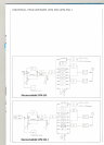
Mains connection and fuses
The UPM 550,(UPM 550,-1) is delivered ex faetory ready for use on mains voltages between 180,-265 V. The line
frequeney may vary between 45 - 60,Hz. Ifthe unit is to be used on power-lines of 90,- 130,V two fuses inside
the instrument have to be ehanged from their holders labelied "220, V" to the holders labelled."11 0,V". This is
done as folIows: Loosen the four Philips serews on the rear of the instrument, remove rear panel and pull out the
instrument by its handles towards the front.
I
I,
On the left side of the main eireuit board, below the power transformer, the four elearly labelied fuse holders are
loeated. These fuses of 0,,16 mA (medium-fast) are used for all mains voltages between 90,and 265 V. The
primary winding of the power transformer consists of two separate windlngs which are paralled for "110, V"
operation. Both windings in this case have their own fuse. In case of "220, V" operation the two windings are
eonnected in series and are fused by the first fuse only. The second fuse in this case serves asaspare sinee it is
not in the circuit. .
If the fuses are inserted into their proper holders the unit can be put to operation after it has been remounted in its
housing.
Operating the UPM
After the UPM 550, has been connected to the mains the mechanical zero of the pointer should be checked and
eorreeted - if neeessary - by means of the adjuster (4). A suitable i;lput eable with BNC-conneetors is connected
to socket (16) "Input". Now switch on the unit by pressing switeh (1). The green LED above the switch will light
up and the pointer will move for a short moment. Until the cireuits are completely stabilized the indicating meter
will remain switehed-off. An automatie eircuit eonnects the meter back after approximately 12 seconds. The
instrument is now ready to be used. All LED's for the ranges and modes now show the seleeted mode of
operation. Ifthe reserve positions "Res. 1" and "Res. 2" are not fitted with a plug-in filter board the instrument
remains switched-off as long as either button "Res 1" or "Res 2" 13 is pressed.
\
I
Test
The fun'ctionof all amplifiers and the panel meter may be tested by the built-in test oscillator as foliows: Select
- 70,dB (TEST) on the range switeh (17), press button (15) TEST. The pointer must now indieate 0,dBv ::t 3%
(0,dBm at UPM 550,-1). As long as the TEST-position is selected an audio signal of 10,0,mV is available at the
60,Q output (2) and a signal of 1 V at the 60,0,Q output (3).
The frequency of the test tone is 10,0,0,Hz. The frequeney stability is very high making this signal suitable for all
kinds of external test applieations. The !lV-range will tolerate momentary accidental voltages up to 10,V.
If 10,VRMS is exceeded, the amplifier may become .defective. In this case measurements may, nevertheless,
continueinthe mVandV-ranges.Totestthese rangesthe rangeswiteh(17) may be brought in the position
- 60,dB and the test oscillator, switeh (15), may be inserted. The meter will now indicate -1 0,dBv
(-10, dBm at UPM 550,-1).
After test always release the button TEST (15) for the following measurements.
1
J
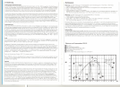
Measurements
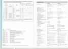
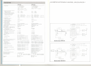
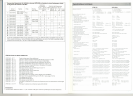
Table 1 gives all possible measurements with the UPM 550, depending on the frequency range of the
selected mode of rectifieation, the measuring range and the inserted filter. Two LED's below the range switeh
indicate automatically the usable frequeney range.
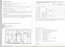
Peak rectifieation is seleeted with switeh (5) and RMS-rectification through switch (6). The necessary filter is
seleeted by means of the set of buttons (8 -14). If measurements without any filter are to be made switeh (7)
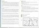
OFF must be pressed. The frequeney characteristic of the filter!>is shown graphically on the rear panel of the
instrument.
The measuring ranges are selected by the rotary switeh (17) qetween 30,0,V and 30,!lV in steps of 10,dB. The
upper voltage scale of the meter (ranges 10,0,V, 10,V, 1 V, 1aG,mV, 10,mV, 1 mV, 10,0,!lV) eorresponds with the
indication of the upper row of red LED's in the field of the rangeswiteh and the lower voltage seale (ranges 30,0,V,
30,V, 3 V,30,0,mV, 30,mV, 3 mV, 30,0,!lV, 30,!lV) with the lower line ofthe red LED's. This eases and speeds up the
readings when changing ranges.
r