4 5
C o m p o n e n t s
Components
Components
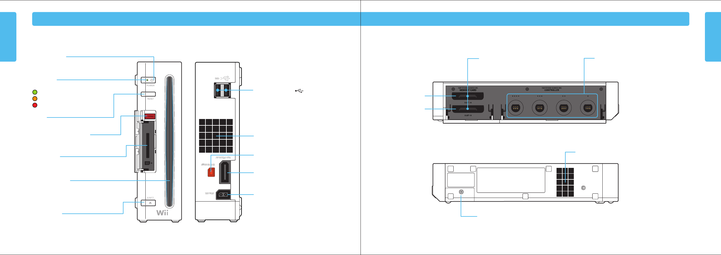
POWER Button
Press to turn the console ON or OFF.
NOTE: The Power LED does not go out when the
power is turned off.
USB Connectors
Connects to USB devices, such as the Wii
LAN Adapter. (Sold separately.)
Do not connect any device that is not
specifically designed for use with
the Wii System.
Nintendo GameCube Memory Card Slots
For use with Nintendo GameCube Memory Cards.
Battery Cover
For access to CR Coin Lithium battery (CR2032). Perchlorate Material – special handling may apply.
More information can be found at http://www.dtsc.ca.gov/HazardousWaste/Perchlorate/index.cfm.
Do not remove battery cover unless instructed to do so by a Nintendo Customer Service representative.
Air Intake
Nintendo GameCube Controller Sockets
For use with Nintendo GameCube Controllers.
Air Vent
Do not block.
AV Multi Out Connector
Connects to the AV cable for your television.
Sensor Bar Connector
Connects to the Sensor Bar.
DC Input Connector
Connects to the Wii AC Adapter.
Power LED
Shows the status of the Wii console.
Green - Console power is ON.
Orange - Standby mode , WiiConnect24 is ON.
Red - Standby mode, WiiConnect24 is Off.
RESET
Press to restart a game.
SYNCHRO Button (SYNC.)
Used when synchronizing a Wii Remote
with the console. See pages 20-21.
SD Card slot
For inserting an SD memory cards.
See page 30.
EJECT Button
Press to eject a Wii or Nintendo
GameCube Disc.
Game Disc slot
For inserting a Wii or Nintendo GameCube Disc.
Slot lights blue and blinks when a disc is inserted.
When WiiConnect24 is set to ON, the slot will blink
when messages or data are received.
Slot A
Slot B
1234
Wii Console Wii Console
Wii Operations Manual
148Hx210W


