


— 4 — — 5 — — 6 —
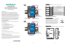
5. Connector Description
Power Connector
Connect the 12 to 48 VDC LPS or Class 2 power line to the
UC-7122/7124’s terminal block. If the power is properly supplied, the
Power LED will light up. The OS is ready when the Ready LED glows a
solid green.
Grounding the UC-7122/7124
Grounding and wire routing help limit the effects of noise due to
electromagnetic interference (EMI). Run the ground connection from the
ground screw to the grounding surface prior to connecting the power.
ATTENTION
This product is intended to be mounted to a well-grounded mounting
surface, such as a metal panel.
SG
SG: The Shielded Ground (sometimes called
Protected Ground) contact is the left most contact
of the 3-pin power terminal block connector when
viewed from the angle shown here. Connect the SG
wire to an appropriate grounded metal surface.
Ethernet Ports
The 10/100 Mbps Ethernet port uses RJ45 connectors.
PIN Signal
1 ETx+
2 ETx-
3 ERx+
6 ERx-
18
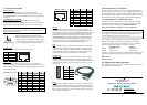
Serial Ports
The serial ports use DB9 connectors for the UC-7122, and RJ45
connectors for the UC-7124. Each port can be configured by software for
RS-232, RS-422, or RS-485. The pin assignments for the ports are shown
in the following table:
DB9 Male (UC-7122)
12345
6789
Pin RS-232 RS-422
RS-485
(4-wire)
RS-485
(2-wire)
1 DCD TxDA(-) TxDA(-) ---
2 RxD TxDB(+) TxDB(+) ---
3 TxD RxDB(+) RxDB(+) DataB(+)
4 DTR RxDA(-) RxDA(-) DataA(-)
5 GND GND GND GND
6 DSR --- --- ---
7 RTS --- --- ---
8 CTS --- --- ---
RJ45 (UC-7124)
18
Pin RS-232 RS-422 RS-485
1 DSR --- ---
2 RTS TxD+ ---
3 GND GND GND
4 TxD TxD- ---
5 RxD RxD+ Data+
6 DCD RxD- Data-
7 CTS --- ---
8 DTR --- ---
SD Slot
The UC-7122/7124 have internal SD slots for storage expansion. To
install an SD card, first use a screw driver to remove the SD slot cover to
access the slot. The slot is located on the right panel of the UC-7122/7124.
Plug the SD card directly into the socket, and then replace the SD slot
cover. When an SD card is inserted, the system will create a directory
called StorageDisk for accessing SD storage. To remove the SD card
from the slot, press the SD card in slightly with your finger, and then
remove your finger to cause the card to spring out partially. You may
then grasp the top of the card with two fingers and pull it out.
USB
The UC-7122/7124 has one USB 2.0 host port located on the top panel
for storage expansion. When a USB storage device is plugged in, the
system will create a directory called StorageDisk for accessing the data
stored on the device. If there is already an SD card in the SD slot, the
system will name the newly created directory “StorageDisk2”.
Console Port
The serial console port is an RS-232 port that uses a 4-pin pin-header
connector. The port is designed for serial console terminals, which are
useful for viewing boot-up messages. Use the CBL-4PINDB9F-100 cable
included with the product to connect a PC to the U-7122/7124’s serial
console port.
4
3
2
1
Pin Signal
4 GND
3 NC*
2 RxD
1 TxD
*NC=Not Connected
Reset
Press the “Reset ” button and hold it in for at least 5 seconds to load the
factory default configuration. After the factory default configuration has
been loaded, the system will reboot automatically. The Ready LED will
blink on and off for the first 5 seconds, and then maintain a steady glow
once the system has rebooted.
6. Powering on the UC-7122/7124
To power on the UC-7122/7124, connect the “terminal block to power
jack converter” to the UC-7122/7124’s DC terminal block (located on the
left side of the top panel), and then connect the power adaptor. Note that
the Shielded Ground wire should be connected to the right most pin of the
terminal block. Once the system is ready, the Ready LED will light up.
7. Connecting the UC-7122/7124 to a PC
There are two ways to connect the UC-7122/7124 to a PC: (1) through
the serial console port, and (2) by Telnet over the network. The COM
settings for the serial console port are: Baudrate=115200 bps,
Parity=None, Data bits=8, Stop bits =1, Flow Control=None.
ATTENTION
Use the CBL-4PINDB9F-100 cable included with the product to connect
a PC to the UC-7122/7124’s serial console port. Remember to choose
“VT100” terminal type for the connection settings.
To use Telnet, you need to know the UC-7122/7124’s IP address and
netmask. The default LAN settings are shown below. For first-time
configuration, you may find it convenient to use a cross-over Ethernet
cable to connect directly from the PC to the UC-7122/7124.
Default IP Address Netmask
LAN 1 192.168.3.127 255.255.255.0
LAN 2 192.168.4.127 255.255.255.0
Once the UC-7122/7124 is powered on, the Ready LED will light up. Use
the following default login name and password to proceed. The defaults
are:
Login: admin
Password: admin
8. Configuring the Ethernet Interface
Please refer to the UC-7122/7124 User’s Manual for information on how
to configure the Ethernet interface.
Copyright © 2007
Moxa Systems Co., Ltd.
All rights reserved.
Reproduction without permission is prohibited.
Tel: +886-2-2910-1230 www.moxa.com
Fax: +886-2-2910-1231 support@moxa.com