


— 5 —
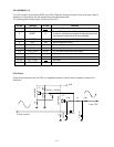
Power Amplifier (LA4598)
The power amplifier is a 2-channel power amplifier with a standby switch.
The following table shows the pin functions of the power amplifier.
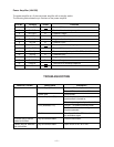
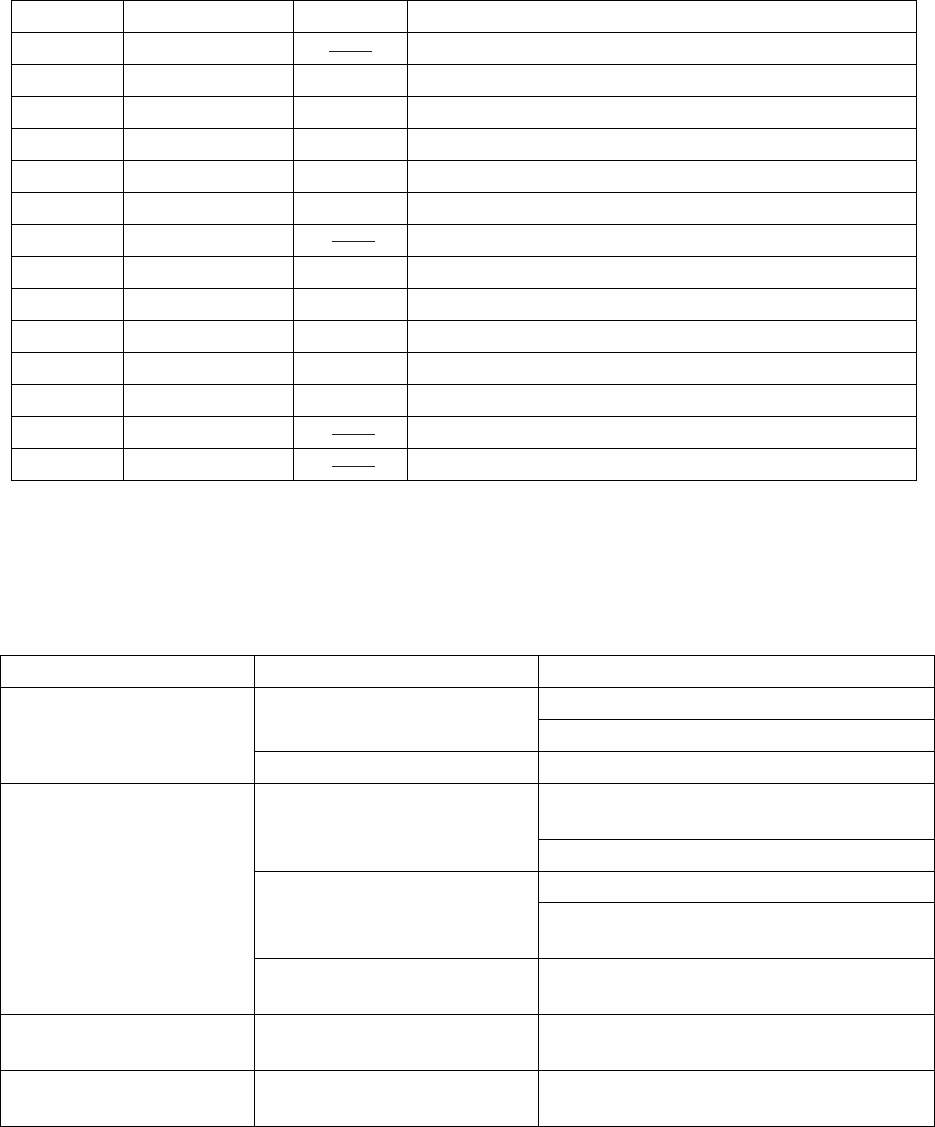
TROUBLESHOOTING
Nature of Trouble Faulty Block Checkpoint
No power Power Supply Circuit Emitter of T2 should provide +5.5 V.
Base of T2 should receive +6 V.
Power Jack Jack contact.
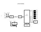
No sound at all Power Amp. (LA4598) Pin 9 should receive +9 V when the
power switch is turned on.
Check output signals of pins 3 and 12.
CPU (MSM6387-13) Pins 21 ~ 30 should provide pulses.
Pin 5 should have a sound signal when
keys are pressed.
Oscillator Pins 8 and 9 of the CPU should receive
an ocsillation signal.
A certain key or switch
does not function
Key and Switch Matrix Dust on the contact.
Certain keys or switches
do not function
Key and Switch Matrix Open circuit on KC or KI line.
Pin No. Terminal In/Out Functiion
1 Power GND Ground (0 V) source
2 Ch1 B.S. Out Terminal for a bootstrap capacitor
3 Ch1 OUT In Channel1 output
4 VCC In +9 V source. Connected to the power source directly.
5 Ch1 N.F. In Negative feedback input
6 Ch1 IN In Channel1 input
7 D.C. Terminal for a decoupling capacitor
8 Pre GND In Ground (0 V) source
9 Standby In Power control signal input. 0 V: OFF, +9 V: ON
10 Ch2 IN In Channel2 input
11 Ch2 N.F. In Negative feedback input
12 Ch2 OUT Out Channel2 output
13 Ch2 B.S. Terminal for a bootstrap capacitor
14 NC Not used.