


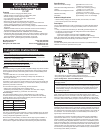

Manually Connect and Disconnect Battery Banks
A control switch such as a Blue Sea Systems Switch Panel PN 8270 may be
used to manually connect and disconnect battery banks by overriding the CL-
Series BatteryLink™ ACR voltage sensing circuit.
• Connect Terminal 2 to the center common terminal of a ON-OFF-ON single
pole, double throw switch.
• Connect negative and positive to the outside terminals of the switch.
To connect a manual override switch:
• When Terminal 2 is switched to the positive supply, the relay is closed
whenever the voltage is greater than about 9 volts at either terminal.
• When Terminal 2 is switched to the negative supply line, the relay is held
open.
• When the switch is in the center position, the CL-Series BatteryLink™ ACR
operates automatically to close and open the relay when it senses the
presence of charging voltages. The control signal to Terminal 2 passes very
little current and can be supplied from any fused positive source.
Remote LED indicator
If you want to be able to determine at a remote location when the battery banks
are connected, a remote LED indicator can be connected to the CL-Series
BatteryLink™ ACR.
• Connect the red wire of the LED to a positive source.
• Connect the yellow wire of the LED to Terminal 4.
To connect an LED indicator:
Suitable LED indicators are Blue Sea Systems 8033 (amber), 8171 (red), or 8172
(green).
When all wiring is complete and has been checked, restore battery connections.
The relay may momentarily energize when power is fi rst applied. The automatic
charging circuit has a time delay of approximately one minute to reduce cycling
caused by noise in the system.
Indicator Lights
There are three LED indicator lights on the CL-Series BatteryLink™ ACR:
• UNDERVOLTAGE
• COMBINED
• OVERVOLTAGE
The amber UNDERVOLTAGE indicator lights when:
• There is no charging source present
• The voltage level of the sensed battery is less than the COMBINED value
• There is a charging source on one battery and the other battery is less
than 4 volts.
The UNDERVOLTAGE indicator is normally on when the batteries are being
discharged. When the UNDERVOLTAGE indicator is on, the battery banks are
disconnected in approximately one minute.
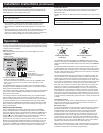
12.2
11.5
14
13.2
12.6
11.9
13.0
12.3
13.5
12.7
13.5 15.5
14.0
14.5
15.0
Combining Adjustment
(close/open)
Overvoltage Adjustment
(open)
The COMBINED potentiometer adjusts the COMBINED voltage to the user’s
preference. Changing the COMBINED setting automatically changes the OPEN
voltage as well because the OPEN voltage is fi xed at 6% below the COMBINED
voltage.
The OVERVOLTAGE potentiometer is used to adjust the voltage at which the
CL-Series BatteryLink™ ACR switch opens in response to high voltage. This is a
protection feature when one battery needs to be charged at a lower voltage than
the other. It also protects the second battery bank in the event of an overvoltage
condition produced by the alternator.
The potentiometer adjustment range covers about 270 degrees of rotation. Do
not use excessive force - this adjustment requires only a little torque within the
rotation range; it should not be forced beyond the end stops. If you do want to
make an adjustment, note the orientation of the screwdriver as you adjust. There
are end stops at approximately 4 O’clock and 8 O’clock and it may be necessary
to turn gently to fi nd those stops and then return to the intended adjustment.
Some high current chargers in inverter/charger systems drive very high current
pulses into the system. The average voltage may be in range, but the peak
voltages may cause the OVERVOLTAGE light to come on. Connecting the CL-
Series BatteryLink™ ACR negative connection and positive connection directly
to the batteries can reduce the effects of voltage drop in the wiring and prevent
these chargers from interfering with the CL-Series BatteryLink™ ACR. It may be
necessary to adjust the OVERVOLTAGE setting up to its maximum value if such
a charger is driving a smaller battery system that does not readily accept this rate
of charge.
Undervoltage Lockout
The voltage sensing circuits in the CL-Series BatteryLink™ ACR prevents the
relay from automatically closing if either sensing terminal is connected to a
voltage source at a voltage less than 4 volts.
Emergency Starting
The CL-Series BatteryLink™ ACR is designed for automatic control for charging
dual battery banks. When it is manually closed, it allows a starting battery to
be supplemented by the house battery. However, this use should be limited
to smaller engines. Even occasional use to connect both battery banks for
emergency starting may overstress the relay contacts and reduce life. The CL-
Series BatteryLink™ ACR current limiting system permits high peak currents
for a few seconds, which may be adequate to start a small diesel or a small to
medium sized gasoline engine in good working condition. Also, starting currents
may exceed the capacity of the CL-Series BatteryLink™ ACR’s current limiting
capability, which causes the protective circuit to temporarily open.
Many battery management systems include a manual emergency cross connect
battery switch or a “1-2-Both” battery switch. If either of these are available, it is
preferable to use that device for emergency engine starting.
If the voltage on Terminal A or Terminal 1 remains high enough for approximately
one minute, the green COMBINED indicator lights, the relay closes, and the
battery banks are connected.
If the voltage exceeds the OVERVOLTAGE setting, the red OVERVOLTAGE
indicator lights and, after a few seconds delay, the green indicator goes out.
When the OVERVOLTAGE indicator is on, the battery banks are not connected.
To facilitate adjustment of the CL-Series BatteryLink™ ACR voltage settings,
OVERVOLTAGE and UNDERVOLTAGE indicator lights operate without a time
delay. However, the relay closure only occurs if the voltage is in range for the
period of the time delay.
Adjusting Voltage Settings
The CL-Series BatteryLink™ ACR is preset at the factory for COMBINED
voltage, UNDERVOLTAGE, and OVERVOLTAGE values that are consistent
with typical charging systems and fl ooded lead acid batteries. COMBINED and
OVERVOLTAGE have default settings of 13.5V and 15.0V respectively. The
triangles ( ) on the product label show the normal settings for conventional
charging service. For most systems, no adjustment is necessary.
These values can be changed to meet your specifi c needs. For example, some
batteries such as Gel Cell and AGM are sensitive to overcharging so you may
want to set OVERVOLTAGE lower than nominal. Also, if the ACR is used to
control loads, COMBINE and OVERVOLTAGE can be set downward to shut off
appliances to reserve capacity for starting, navigation, and communication.
Installation Instructions (continued)
Operation
Remote LED
Battery Negative
Manual Switch, ON-AUTO-OFF
Remote Sense for B-Battery
1234
The CL-Series BatteryLink™ ACR has two potentiometers to adjust these
settings to the user’s preferences.