


AMX Corporation reserves the right to alter specifications without notice at any time.
For full warranty information, refer to the AMX Instruction Manual(s) associated with your Product(s).
060-004-2692 8/04 ©2004
AMX Corporation. All rights reserved. The AMX logo is a trademark of AMX Corporation. AMX reserves the right to alter specifications without notice at any time.
3000 RESEARCH DRIVE, RICHARDSON, TX 75082 • 800.222.0193 • fax 469.624.7153 • technical support 800.932.6993 • www.amx.com
93-2105-03
REV: B
Connections and Wiring
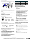
FIG. 2 shows the layout of the connectors and components located on the rear
of the NI-700 NetLinx Integrated Controller.
Wiring a power connection
Use any standard PSN power supply (usage dependent) to supply power to the
NI-700 through the 2-pin 3.5 mm mini-Phoenix connector on the rear panel
(FIG. 2).
The incoming PWR and GND cable from the PSN power supply must be
connected to the corresponding locations within the PWR connector. Refer to
the NetLinx Integrated Controllers Instruction Manual for more detailed wiring
connection information.
RS-232/422/485 wiring connector information
FIG. 3 shows the pinout and wiring specification information for the rear
RS-232/RS-422/RS-485 (DB9) Device Ports. These ports support most
standard RS-232 communication protocols for data transmission
(NI-700 uses Ports 1 & 2).
Ethernet 10/100 Base-T Connector
A standard CAT5 Ethernet cable provides 10/100 network connectivity between
the Integrated Controller and the network (FIG. 4).
Note: On Netlinx Masters (such as those aboard the NI-700), from within the
Telnet or Terminal applications; you can send the SET ETHERNET MODE
command to assign the speed of your Ethernet connection.
Sample NI-700 command:
SET ETHERNET MODE AUTO
The NI-700 only allows you to set the Ethernet mode to AUTO negotiate
the Ethernet connection speed. Using any of the other connection modes
(10 Half/Full or 100 Half/Full) results in an error message.
Program Port Baud Rate Settings
The Configuration DIP switch is located on the front panel. Use this DIP switch
to set the baud rate for the Program Port, according to the settings shown in the
following table. Make sure the baud rate you set matches the baud rate on your
PC's NetLinx COM Settings before programming the unit.
By default, the baud rate is set to 38,400 (bps).
Note: DIP switch 1 activates/deactivates the Program Run Disable Mode. DIP
Switches 2,3, and 4 must remain OFF at all times.
Setting the Configuration (Program Port) DIP Switch
1. Disconnect the power supply from the rear 2-pin PWR (green)
connector.
2. Set DIP switch positions according to the information listed in the previous
Baud Rate Settings table.
3. Reapply power to the unit.
Preparing the NI-700 for Communication
1. Launch NetLinx Studio 2.2 (default location is Start > Programs > AMX
Control Disc > NetLinx Studio > NetLinx Studio 2.2).
2. Select Settings > Master Communication Settings, from the Main
menu, to open the Master Communication Settings dialog box.
3. Click the Communications Settings button to open the
Communications Settings dialog.
4. Click the NetLinx Master radio button (from the Platform Selection
section) to indicate that you are working with a NetLinx Master
(NI-Series of Integrated Controllers).
5. Click the Serial radio button (from the Transport Connection Option
section) to indicate you are connecting to the Master via a COM port.
6. Click the Edit Settings button (on the Communications Settings
dialog) to open the Serial Settings dialog and set the COM port
parameters for the COM port being used to communicate to the NetLinx
Master.
7. Click the OK button three times to return to the main application.
8. Right-click within the Online tab and select Refresh System.
9. Assign a System Value by using Diagnostics > Device Addressing from
the Main menu and enter the new and current system values.
10. Click the Change Device/System Number button and when finished
click Done.
11. Select Tools > Reboot the Master Controller > Continue to restart the
Master and incorporate any changes.
Communicating with the Integrated Controller via Ethernet
Once the NI-700 has been configured according to the steps outlined above, it
is ready for Ethernet communication:
1. Connect an Ethernet cable to the units’ rear Ethernet connector.
2. Select Diagnostics > Network Address from the Main menu and either
use the:
- GET IP button (to obtain a DHCP Address from the DHCP Server),
click SET IP to assign the new address and then press the Done button to
finish the process.
- SET IP button (to set/specify a pre-reserved IP Address to the
Master), click this button and then press the Reboot Master button to
restart the Master and incorporate any changes.
3. Repeat steps 2 - 4 from the above section.
4. Click the TCP/IP radio button (from the Transport Connection Option
section) to indicate you are connecting to the Master via an IP.
5. Click the Settings button.
6. Enter the TCP/IP Address (either the obtain or assigned address) from
step 2.
7. Click the OK button three times.
8. Right-click within the Online Tree tab and select Refresh System.
FIG. 2 NI-700 rear connectors and components
FIG. 3 RS-232/422/485 DB9 (male) connector pinouts
FIG. 4 Layout of Ethernet LEDs
IR RX
GND
I/O
PWR
4 23 1
IR
AXlink
GND
AXP
AXM
PWR
PWR
12VDC
PORT 2 PORT 1
ETHERNET
10/100
L/A SPD
GND
IR IN
AUX
+12V
AXLink LED
IR RX
RS-232/422/485 (Ports 1 & 2)
I/O (Port 4)
IR/Serial
Rear
(green)
(Port 5)
Ethernet
AXLink
port
PWR
(Port 3)
5
4
3
2
1
9
8
7
6
Male
DB9 Serial Port pinouts (male connector)
Pin 2: RX signal
Pin 3: TX signal
Pin 5: GND
Pin 7: RTS
Pin 8: CTS
RS-232
Pin 1: RX -
Pin 4: TX +
Pin 5: GND
Pin 6: RX +
Pin 9: TX -
RS-422
Pin 1: A (strap to 9)
Pin 4: B (strap to 6)
Pin 5: GND
Pin 6: B (strap to 4)
Pin 9: A (strap to 1)
RS-485
ETHERNET
10/100
L/A SPD
SPD - Speed LED lights (yellow) when
and turns Off when the speed
is 10 Mbps.
the connection speed is 100 Mbps
L/A - Link/Activity LED lights
(green) when the Ethernet
cables are connected and
terminated correctly.
Baud Rate Settings
Baud Rate Position 5 Position 6 Position 7 Position 8
9600 bps OFF ON OFF ON
38,400 bps (default) OFF ON ON ON
57,600 bps ON OFF OFF OFF
115,200 bps ON ON ON ON