1 - General Information
12
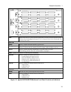
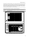
RS-232
PORT A
RS-232
PORT B
A
B
C
D
E
F
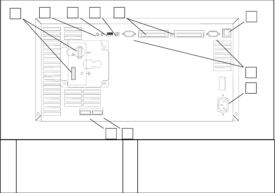
+ and - Power bus connectors
(- bus bar is connected to chassis ground)
Calibration status LEDs
Configuration switches
Transfer Calibration switch
Digital I/O connectors
LAN connection
G
H
J
K
RS-232 connectors (ports A and B)
AC line connection (a universal AC input for line
voltages from 87 Vac to 250 Vac, 50/60 Hz.)
Auxiliary output connection
Calibration port
Figure 1-3. Agilent E4370A MCCD Mainframe Rear Panel Connections
Agilent E4374A and E4375A 64-Channel Charger/Discharger Cards
The Agilent E4374A and 4375A 64-Channel Charger/Discharger cards contain the circuitry that
independently charges and discharges each cell connected to the front of the mainframe. Up to four
identical-model cards can be installed in each mainframe. Agilent E4374A cards charge cells at at up to
5V and 2A. Agilent E4375A cards charge cells at up to 5V and 3A.
Each output channel has a maximum available compliance voltage of 5.5V for Agilent E4374A cards and
6.0V for Agilent E4375A cards. Compliance voltage is defined as the voltage required at the cell plus
any fixture/wiring voltage drops. Having this higher compliance voltage allows the full programmable 5
V to be applied directly to the cell with up to 0.5-volt loss in the wiring for Agilent E4374A cards and up
to 1.0-volt loss in the wiring for Agilent E4375A cards.
Agilent E4371A Powerbus Load
For the discharging cycle, an Agilent E4371A Powerbus Load is required to dissipate excess power from
discharging cells. The load operates in constant voltage mode only and sequentially switches internal
resistors on and off to regulate the voltage on the power bus around a midpoint of 26.75 volts. The
number of load units required depends on the number of Agilent MCCD mainframes in your system.
Each Agilent E4371A Powerbus Load is capable of the dissipating the full power from eight Agilent
E4374A 64-Channel Charger/Discharger cards or eight Agilent E4375A 64-Channel Charger/Discharger
cards.
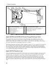
A
B C D E
G
F
H
K J


