25
Installation Instructions
Components
The images shown in this installation instructions are for illustrative purpose only.
Check the supplied components before starting.
Commercially available components (not supplied)
≥ Screws for wall mounting
≥ Fall prevention cord
≥ Screws to attach fall prevention cord to wall
≥ Use commercially available screws with a nominal diameter of ‰4.0 mm that are suited to the wall material (wood, steel frame,
concrete etc.) you are attaching the wall mount brackets to.
≥ Product numbers correct as of May 2010. These may be subject to change.
Installation procedure
Never use any other method than specified to install
Preparation
≥ To prevent damage or scratches, lay down a soft
cloth and perform the assembly on it.
≥ Keep the screws out of reach of children to
prevent swallowing.
≥ Do not hold this unit in one hand to avoid injury by dropping this unit when carrying.
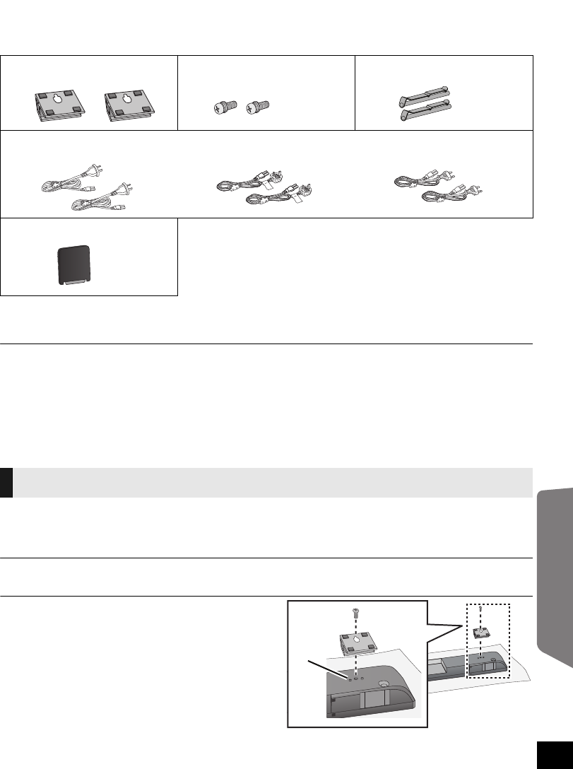
1 On the rear of the unit:
Place the wall mount bracket by
aligning the holes in the wall mount
bracket with the projecting parts A.
2 Screw the wall mount bracket firmly
into place.
≥ Screw tightening torque: 80 N0cm to
120 N0cm.
≥ Repeat the steps above when installing the second wall mount bracket.
∏ 2 Wall mount brackets ∏ 2 Screws ∏ 2 Lock pins
∏ AC mains leads
(Australia and New Zealand)
(Saudi Arabia and Kuwait) (Others)
∏ 1 Digital transmitter
Attaching the wall mount brackets
SCHTB500EGGNGS_RQTX1185-B.book Page 25 Wednesday, July 7, 2010 5:18 PM


