


QUICK INSTALLATION GUIDE
Remote Management Card
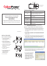
RMCARD302
I
ntelligent Remote Management Card allows a UPS
system to be managed, monitored, and configured
K09-0000057-01
INSTALLATION GUIDE
5. Connect the Ethernet cable
to the LAN port of the
CyberPower Remote
Management Card.
6. Turn on the UPS.
4. Re-install and tighten the
retaining screws.
3. Install the CyberPower Remote
Management Card into the
expansion port.
2. Remove the two retaining
screws of the expansion port
cover then remove the cover.
1. Turn off the UPS before
removing the expansion port
cover on the UPS.
Definitions for LED Indicators
Step 2. Configure the IP address for the CyberPower
Remote Management Card.
Method 1: Using the Power Device Network Utility Tool
1. Install the Power Device Network Utility Tool from the included CD. It
is located on the CD in the \tools\nework folder. Double click the
“Power Device Network Utility” installation file, “Setup.msi” to begin
the installation.
2. After installation is completed, run the “Power Device Network Utility”
program. (Under “All Programs”, select “CyberPower Power Device
Network Utility”).
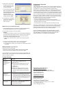
3. The main dialog of the Power Device Network Utility Tool program is
shown in Figure 1. The tool will display all Remote Management
Cards present on the network. The "Refresh" button is used to search
the entire local network again.
4. Select the Remote Management Card you are setting up. Click on the
Tools menu and select “Device Setup” or double click the Remote
Management Card you want to configure.
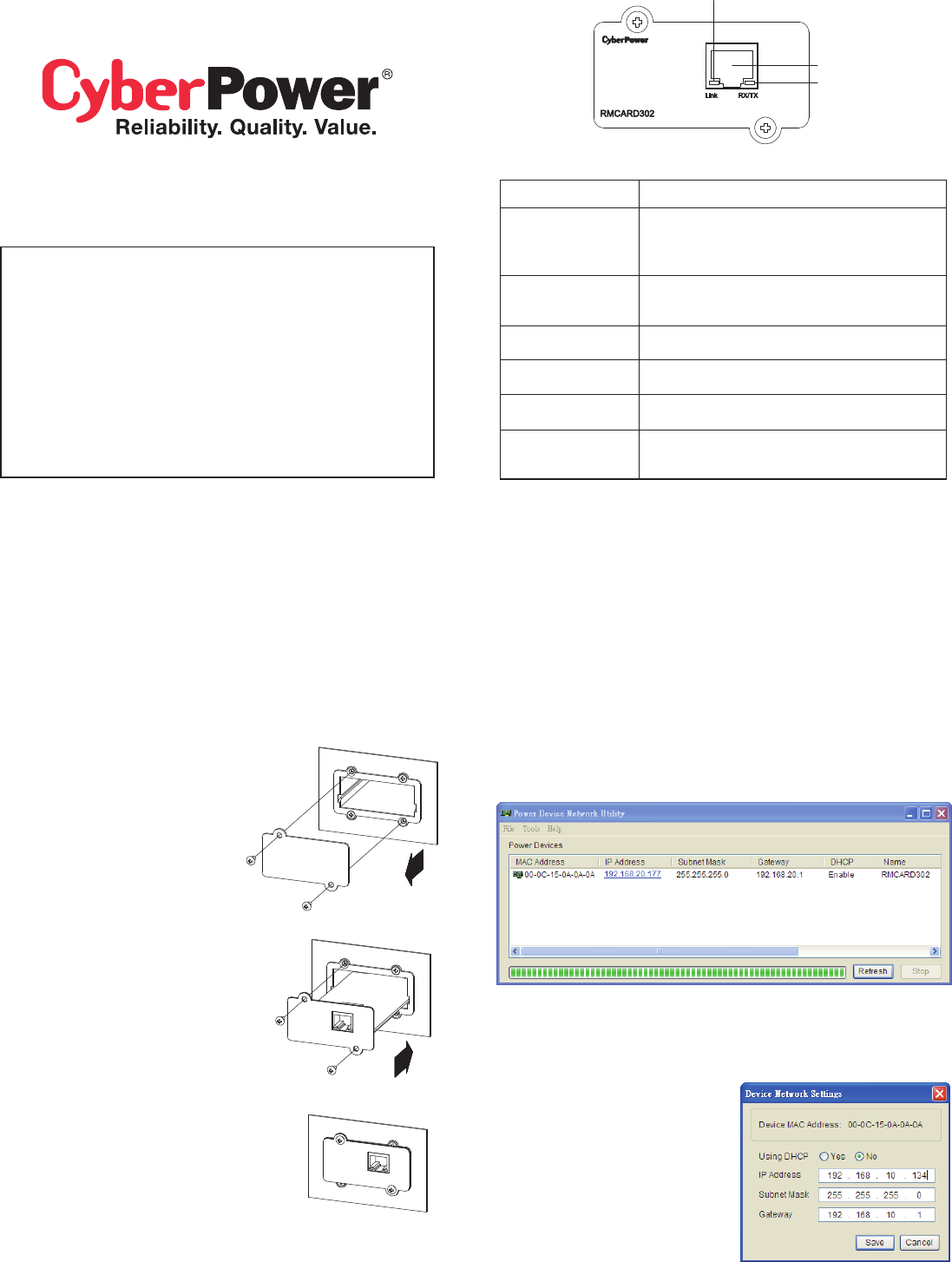
5. You can modify the IP Address,
Subnet Mask, and Gateway
address for the Device MAC
Address listed in the Device
Network Settings window, as
shown in figure 2. The default IP
Address is 192.168.20.177 and
the default Subnet Mask is
255.255.255.0.
Link LED color
Off
On(Yellow)
TX/RX LED color
Off
On(Green)
Flash
Condition
The Remote Management Card is not
connected to the Network or the Remote
Management Card power is OFF
The Remote Management Card is connected
to the Network
The Remote Management Card power is OFF
The Remote Management Card power is ON
- Receiving/transmitting data packet
- Reset finished
LINK Indicator
Ethernet connector
RX/TX Indicator
Step 1. Hardware Installation
Figure 1. The main window of the “Power Device Network Utility” program.
Figure 2. The Device Network setting window.