


Bosch Security Systems | 2007-02 | 9922 141 70691 en
DCN Wireless | Installation and User Instructions | Contribution Devices en | 99
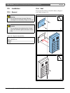
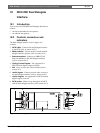
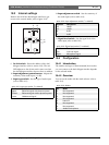
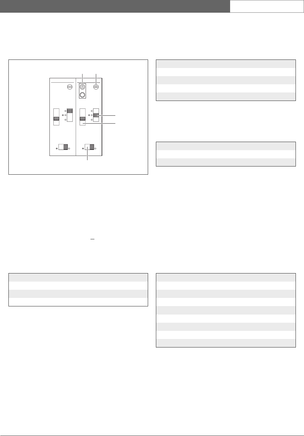
19.3 Internal settings
Remove the lid of the dual delegate interface to get
access to the controls inside (refer to figure 19.2).
9 De-init switch - Erases the address of the dual
delegate interface (refer to section 12.2). The red
LED adjacent to the de-init switch comes on when
the dual delegate interface does not have an address.
10 Input adjustment potentiometer - Adjusts the
sensitivity of the audio input (+
3dB).
11 Input type switch - Sets the type of audio input
(refer to table 19.1).
12 Input adjustment switch - Sets the sensitivity of
the audio input (refer to table 19.2).
13 Signal level switch - Sets the signal level of the
audio input (refer to table 19.3).
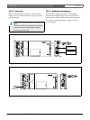
19.4 Configuration
19.4.1 Introduction
The number and types of (flush-mounted) devices that
you can connect to the dual delegate interface depends
on the selected mode.
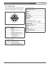
19.4.2 Overview
You can set the mode with the mode selector (refer to
table 19.4).
figure 19.2: Internal settings
table 19.1: Input type switch (* = default)
Position Description
Upper Balanced signal with phantom power
Center* Balanced signal without phantom power
Lower Unbalanced signal*
18
dB
+/-3dB
1
12
6
0
P12
/
18
dB
+/-3dB
2
12
6
0
P12
/
9 10
13
11
12
table 19.2: Input adjustment switch (* = default)
Position Description
18 18 dB
12 12 dB
6* 6 dB
0 0 dB
table 19.3: Signal level switch (* = default)
Position Description
Left Line level signal
Right* Microphone signal
table 19.4: Modes
No. Mode
0 Not supported
1 Not supported
2 Not supported
3 Not supported
4 Intercom
5 Not supported
6 Not supported
7 Ambient microphone