


Bosch Security Systems | 2007-02 | 9922 141 70691 en
DCN Wireless | Installation and User Instructions | Central Devices en | 39
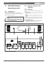
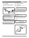
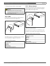
10.2.2 Rear view
The rear of the central control unit (refer to figure 10.1)
contains:
5 RS232 ports - Connects a PC, remote controllers or
video cameras to the central control unit (refer to
10.5.8).
6 Power inlet - Connects the central control unit to
the mains power supply with a power cable (refer to
10.5.1).
7 Ground screw - Connects the central control unit
to ground.
8 Optical network sockets - Connects the central
control unit to the optical network (refer to 10.5.3).
9 DCN sockets - Connect the central control unit to
the DCN (refer to 10.5.2).
10 Fault contact - Connects the central control unit to
devices to sense the condition of the central control
unit (refer to 10.5.7).
11 Audio inputs - Connect the central control unit to
external analog audio sources (refer to 10.5.5).
12 Audio outputs - Connect the central control unit
to external analog audio devices (refer to 10.5.6).
13 Voltage selector - Selects the voltage on which the
central control unit must operate (refer to 10.5.1).
14 Fuse holder - Prevents damage to the internal
power supply unit of the central control unit (refer to
10.5.1).
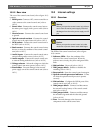
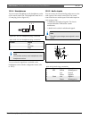
10.3 Internal settings
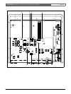
10.3.1 Overview
The PCBs of the central control unit (refer to figure
10.2) contain:
15 Software LEDs - Show the condition of the
software of the central control unit. When the
software runs correctly, the yellow and green LEDs
flash.
16 S600 switches - Reserved (refer to 10.3.2).
17 X605 jumper block - Enables or disables the
watchdog (refer to 10.3.5).
18 Reset switch - Starts the central control unit again.
19 Optical network processor indicator - Comes
on when the optical network processor operates
correctly.
20 S500 switches - Configure the RS232 ports of the
central control unit (refer to 10.3.3).
21 X600 jumper block - Connects and disconnects
the internal back-up battery of the central control
unit (refer to 10.3.4).
22 X104 jumper block - Connects and disconnects
the mechanical ground and the electrical ground
(refer to 10.3.6).
23 Fuse - Prevents damage to the electronic
components in the central control unit.
Warning
Before you open the central control unit, discon-
nect it from the mains power supply. Electrical
discharges from the mains power supply can kill
you.
Caution
Before you open the central control unit, take
measures to prevent electro-static discharges.