


Bosch Security Systems | 2007-02 | 9922 141 70691 en
DCN Wireless | Installation and User Instructions | System Design and Planning en | 26
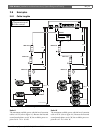
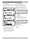
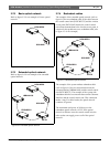
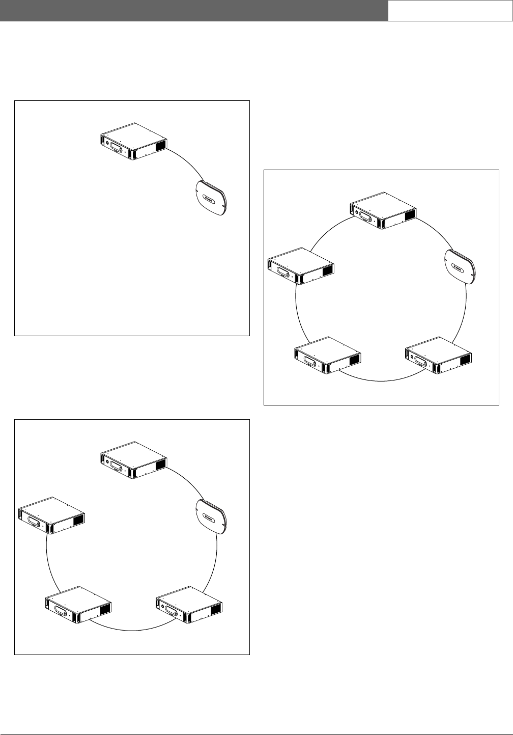
3.7.2 Basic optical network
Refer to figure 3.5 for an example of a basic optical
network.
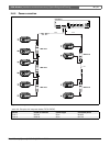
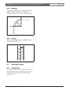
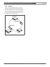
3.7.3 Extended optical network
Refer to figure 3.6 for an example of an extended
optical network.
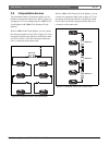
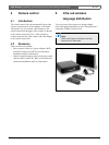
3.7.4 Redundant cables
The example of the extended optical network (refer to
figure 3.6) has no redundant cable. If the cable between
the central control unit (DCN-WCCU) and the wireless
access point (DCN-WAP) breaks, the central control
unit cannot transmit data to the wireless access point. A
solution for this problem is to use redundant cable (refer
to figure 3.7 for an example).
The example of the system without redundant cable
(refer to figure 3.6) has no connection between the
cobranet interface (LBB4404/00) and the central control
unit (DCN-WCCU). The example of the system with
redundant cable has a connection between the Cobranet
Interface and the central control unit. This connection
makes a ring. If a cable breaks, the optical network
continues to operate.
The maximum total power of all devices in the
redundant optical network is 65 W. If the optical
network is defective near the central control unit, the
other socket can supply power to all of the optical
network.
figure 3.5: Basic optical network
figure 3.6: Extended optical network
DCN- WCCU
DCN- WA P
DCN- WCCU
DCN- WA P
LBB 4404/ 00
INT-TX
PRS-4 DEX4
figure 3.7: Redundant optical network
DCN- WCCU
DCN- WA P
LBB 4404/ 00
INT-TX
PRS-4 DEX4