


Bosch Security Systems | 2007-02 | 9922 141 70691 en
DCN Wireless | Installation and User Instructions | Contribution Devices en | 102
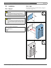
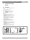
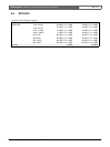
19.6.3 Audio inputs
You can connect microphone or line level signals to the
audio inputs of the dual delegate interface. The audio
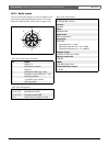
inputs have DIN-8p-262° sockets (refer to figure 19.6).
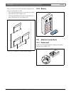
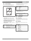
figure 19.6: Audio input, connection
table 19.7: Audio input, connection
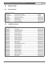
Pin Signal
1 Signal in, +
2 Microphone, common
3 Signal in, -
4 Microphone LED (max. 2 mA)
5 Request-to-speak LED (max. 7 mA)
6 Microphone button
7 +12 V(DC) (max. 20 mA)
8 LED ring control
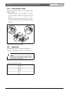
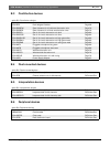
table 19.8: Connections
Pin Component
4 (-) to 7 (+) Microphone on LED
5 (-) to 7 (+) Request-to-speak LED
6 to 7 Momentarily microphone switch
6
7
1
4
8
3
5
2
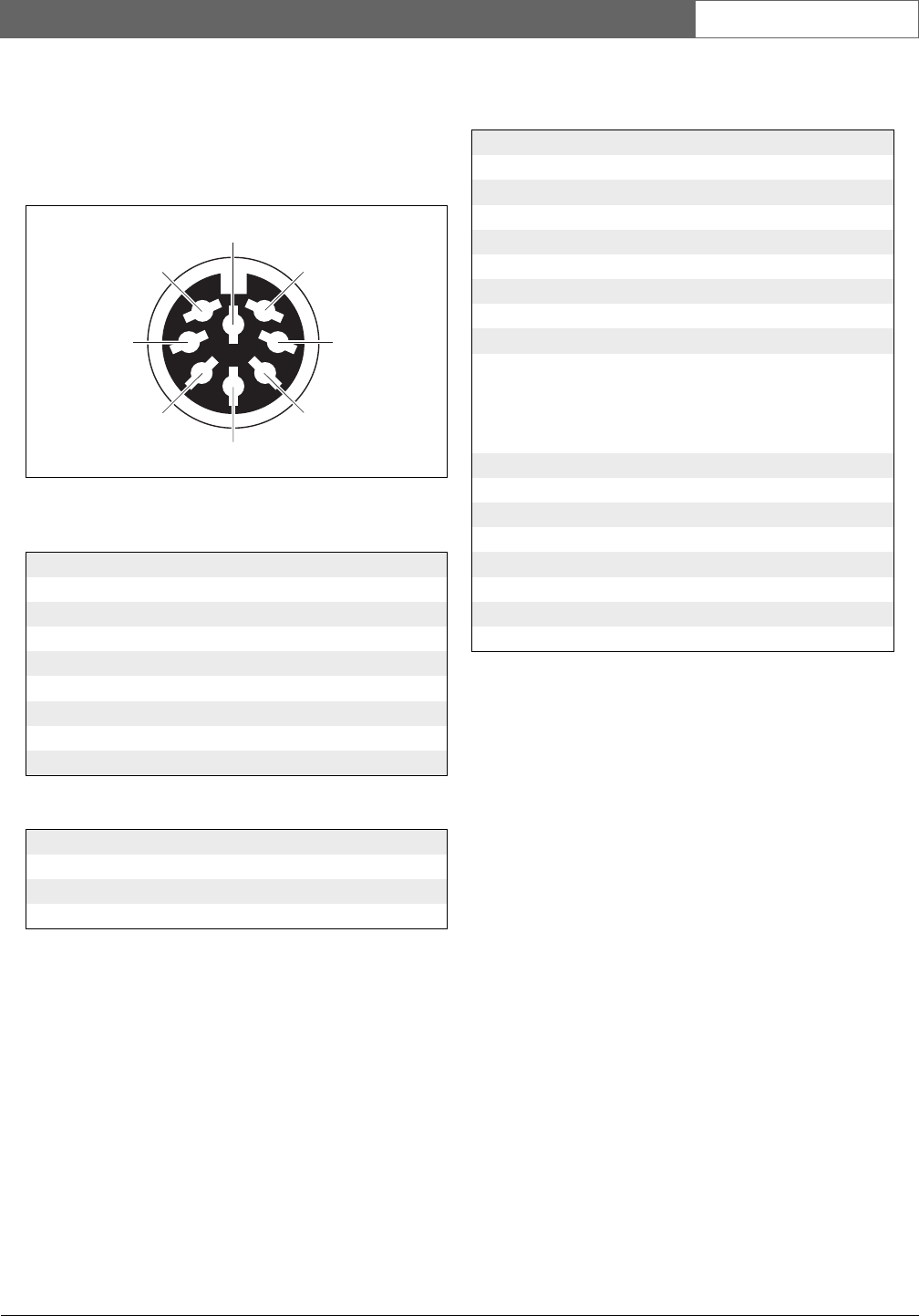
table 19.9: Audio inputs
Number of connections:
2x DIN-8p-262° sockets
Location:
Left side
Cable:
Shielded cable
Audio levels:
Refer to appendix A
Impedance:
Selectable:
• Asymmetric mic.: > 4 kΩ
• Symmetrical dynamic mic.: > 2 x 33 kΩ
• Symmetrical phantom mic.: > 2 x 680 Ω
Phantom supply:
12 V(DC) ± 10%, max. 15 mA
Signal-to-noise ratio:
> 90 dB
CMRR:
> 85 dBA @ max. level
Crosstalk between inputs:
> 40 dB