


Marine Electrical Prod
ucts
CL-Series BatteryLink™ ACR
PN 7600
Features
• Automatic control for charging dual battery banks
• Voltage sensing for charge source on either battery bank
• Remote sensing to avoid voltage drop issues
• Low current draw: less than 12mA open, 175mA closed
• Input fi ltering for noise rejection
• Noise-free circuitry will not interfere with other devices
• Current limiting allows choosing wiring for charging currents without the
need to oversize conductors for connected load currents
• Adjustable COMBINING (automatic connecting) voltage and OVERVOLTAGE
disconnect
• UNDERVOLTAGE lockout to prevent automatic closure if second battery is
discharged below 4 volts (when using dual voltage sensing)
• Indicators for UNDERVOLTAGE, COMBINED, and OVERVOLTAGE
• Internal time delay prevents relay action for transient conditions, voltage must
be within range for approximately one minute to cause closure, relay will open
when overvoltage is detected for approximately 15 seconds.
• Meets SAE J1171 - External ignition protection requirements
Installation Instructions
Mounting
• Select a mounting location near the battery banks or the battery switch.
• Choose a cool, dry, and well-ventilated location if possible. The CL-Series
BatteryLink™ ACR may become very warm when operating at full current
capacity or in current limiting mode.
• Avoid locations directly above batteries where corrosive fumes may be present.
• Do not mount directly to a conductive surface because of the proximity of
the mounting screws to the main electrical terminals.
• Mount the relay securely with #8 or M4 screws.
Wiring
Use interconnecting wiring that provides acceptable voltage drops at the intended
charging currents. Wiring should have at least 60 Amp current-carrying capacity
to be compatible with the current limiting feature of the CL-Series BatteryLink™
ACR. Use:
• At least 8 AWG wire for a connection length of 6 feet or less
• At least 6 AWG wire or larger, according to voltage drop calculations, for
runs longer than 6 feet
ABYC E-11 recommends circuit protection within 7 inches of each battery
connection or source of power. Circuit protection may be as far as 40 inches from
a source of power other than a battery, or 72 inches from a battery if the wiring is
protected by a sheath or enclosure.
To avoid nuisance tripping or fuse blowing, the wire should be:
• Sized to carry the full capacity of the charging source
• Protected by a time-delay fuse (e.g., Bussmann TFC rated 75A or larger)
or thermal circuit breaker (e.g., Bussmann 187 rated 150A).
Current-limiting
The current-limiting feature of the CL-Series BatteryLink™ ACR prevents
excessive current from fl owing through it and can be treated as a self-limiting
protective element. The current handling capacity is shown in this table. Time
delay allows brief currents up to 150 Amps.
Time Current Rating
Continuous 60 Amperes
7 Minute 90 Amperes
2 Minute 120 Amperes
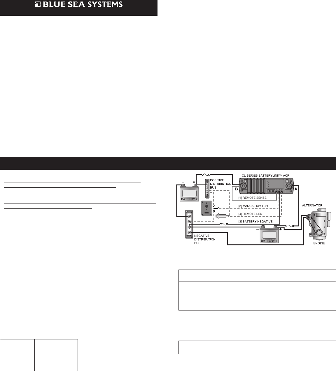
Typical Confi guration - Sense One Battery Bank
• Connect Terminal A to the battery bank connected to the charging source.
• Connect Terminal B to the battery bank not connected to the charging source.
• Connect Terminal 3 to the main negative bus or the negative terminal of the
nearest battery, through a 10-15 amp in-line fuse, to prevent fault current
from fl owing in this wire.
To sense the voltage level of the battery bank connected to your boat’s
charging source:
Sense Both Battery Banks
When charging sources are attached to both battery banks, the CL-Series
BatteryLink™ ACR can be connected to sense the voltage levels of both battery
banks. Use this confi guration, for example, when the alternator is connected to
one battery bank, and the battery charger is connected to the other battery bank.
• Connect Terminal 1 to Terminal B with a jumper wire.
To sense both batteries banks:
Confi guring the CL-Series BatteryLink™ ACR to sense both battery banks also
establishes Undervoltage lockout. This lockout prevents automatic connection of
both battery banks if the second battery bank is discharged below 4 volts. When
the voltage levels of the battery banks are considerably different, they should not
be connected -- the current through the CL-Series BatteryLink™ ACR may be
high enough to fuse the internal relay.
If the voltage drop in the line connected from the battery bank to Terminal B is
expected to be less than 3%, connecting Terminal 1 to Terminal B with a short
jumper is suitable. If voltage drop is expected to be more than 3%, for example,
when connecting widely separated batteries, mount the CL-Series BatteryLink™
ACR near the battery bank connected to Terminal A and use a sensing wire from
terminal 1 to the battery bank connected to Terminal B. The remote sensing wire
carries less than 0.2A when the relay is closed so this conductor can be 16 AWG
and should be protected against faults with a suitable fuse (any value between 2
and 20 Amps) at the battery connection.
Guarantee
Any Blue Sea Systems product with which a customer is not satisfi ed may be
returned for a refund or replacement at any time.
• Gray dashed [2] and [4] lines indicate optional connections
• Gray solid [1] line indicates a recommended but not required connection
Specifi cations
Automatic Combined Voltage Adjustable from 12.2V to 14V
•
Preset to 13.5 (13.4 to 13.6)
Automatic Undervoltage Disconnect 6% Lower than combining (closing)
voltage
•
Preset to 12.7 (12.6 to 12.8)
Automatic Overvoltage Disconnect Adjustable from 13.5V to 15.5V
•
Preset to 15.0 (14.85 to 15.15)
ON/OFF Time Delay Approximately 1 min. for charge/discharge
OFF Delay Approximately 15 sec. for overvoltage
Additional Applications
• Remote battery charging for anchor windlass, bow thrusters, nav station
• Load control to prevent over discharge
Description
The CL-Series BatteryLink™ ACR connected into your boat’s electrical system
provides automatic control for charging dual battery banks. The ACR has two
parts:
• A relay - a switch that is activated by an electrically powered magnetic coil.
• An electronic circuit that senses the voltage level of the boat’s batteries
and signals the relay to switch:
- Closed when voltage is high (the ACR’s COMBINE voltage)
- Open when voltage is lower (the ACR’s UNDERVOLTAGE voltage)
When the voltage level of the battery bank being charged reaches a certain level,
both battery banks are automatically connected and charged.
Electrical Connections
The wiring confi guration below represents a common installation but is not meant
to be a guide for any specifi c vessel. Consult a marine electrical professional for
a wiring confi guration applicable to your boat.
Disconnect the positive battery connections before beginning the installation. If
there is a possibility of tools causing a short to grounded metal or conductors,
disconnect the negative terminals before disconnecting the positive terminals.
Blue Sea Systems Inc. Phone (360) 738-8230
425 Sequoia Drive Fax (360) 734-4195
Bellingham, WA 98226 USA E-mail conductor@bluesea.com
www.bluesea.com
6330 Rev.005