


Quick Hardware Installation Guide
English
MAN-940-QH
01-04-07
MegaRAC G4 card
(Series 940)
Thank you for purchasing the MegaRAC G4 card. Please take a few minutes to
review this quick guide before beginning the installation process. If you require a
further explanation of any item covered in this guide, please refer to the installation
instructions on your MegaRAC G4 CD.
Contents for the MegaRAC G4 card
You should have received the following:
• an American Megatrends MegaRAC® G4 card
• a MegaRAC® G4 card Quick Installation Guide
• this MegaRAC® G4 User’s Guide (located on the MegaRAC® G4 CD)
• a MegaRAC® G4 CD
• a VGA Splitter Cable
• a MegaRAC G4 USB Cable with a power jack input for the AC Adapter
• MegaRAC® G4 feature connector cable
• an AC Adapter (Optional)
Technical Support
If you need help installing, configuring, or running the MegaRAC G4 card, call
American Megatrends technical support at 770-246-8645.
Technical Support Web Site: http://www.ami.com/support/
Technical Support Email: support@ami.com
Hardware Installation
Use the following steps to install the MegaRAC G4 card.
Step Action
1 Unpack the MegaRAC G4 card (and check jumper settings)
2 Plug in the MegaRAC G4 card into the host system and attach internal
cables
3 Connect external cables
4 Confirm the motherboard’s BIOS settings
5 Initial configuration of the MegaRAC G4 card
6 Install/Boot to an Operating System
Note: The AC Adapter (optional) continues to provide power to the MegaRAC
card in the event that the host system is on standby mode (3.3V STB) or
powered on.
Step 1 Unpack the MegaRAC G4 card (and check jumper settings)
Inspect the cardboard carton for obvious damage. If damaged, call 770-246-8600.
Leave it in its original packing.
Jumper Setting
J5 Confirm that no jumper is installed (pins one and two, open).
J14 & J15 If your hosts system’s motherboard has support for I2C on the PCI slots,
place a short pins one and two. If not, confirm that no jumper is installed
(pins one and two, open).
J16 & J17 Verify that these two headers are each shorted with a jumper. If J16 and J17
are not shorted, short pins one and two on both J16 and J17.
Note: J14 and J15 can be used in place of the MegaRAC Feature Cable to gather
I2C bus information from the motherboard.
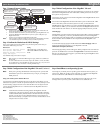
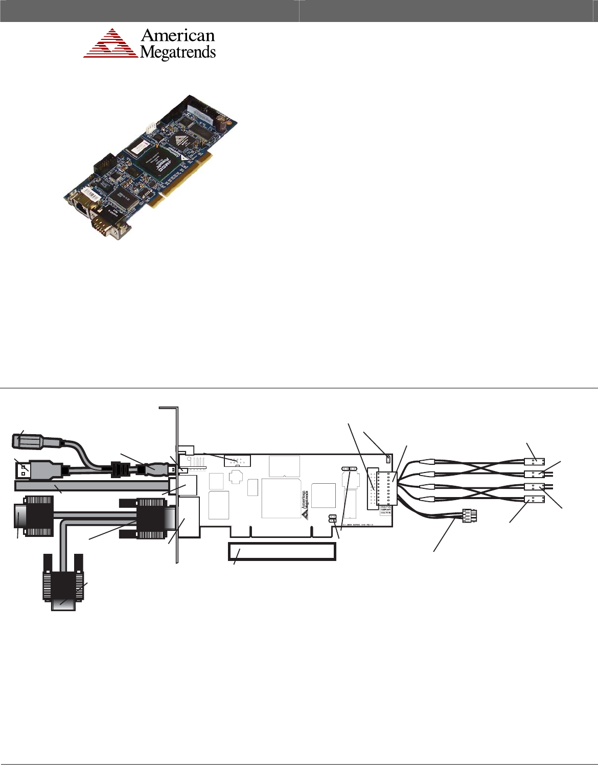
MegaRAC G4 Card Layout and Connection Guide
USB In
Network
VGA In
J10 RS232 Serial Port
J5 Recovery/ Configuration
J18 MegaRAC Feature Connector
J16 & J17 Must Be Shorted
J14 & J15 I2C Clock/Data PCI Bypass
Host System’s Motherboard PCI Slot
VGA Splitter Cable
RJ-45 Network Cable
Plug the AC Adapter here (optional)
To the MegaRAC G4
(USB In)
To Host System’s USB Port
Power On Cable
(Runs between
the MegaRAC G4
and the Power On
Switch located
on Front Panel of
the Host System)
Power On Cable
(Runs between the
MegaRAC G4 and the
Power On Header located
on the Host System’s
Motherboard)
Reset Switch Cable
(Runs between
the MegaRAC G4
and the Reset
Switch located
on Front Panel of
the Host System)
Reset Switch Cable
(Runs between
the MegaRAC G4
and the Reset
Header located
on the Host
System’s
Motherboard)
I2C Cable
(Optional, with Limitations. Runs between the
MegaRAC G4 and the IPMB Header located
on the Host System’s Motherboard)
To the Monitor
(15-pin Female)
To the MegaRAC G4
(15-pin Female)
To the Host System’s
VGA Port
(15-pin Male)
MegaRAC Feature
Connector Cable
(not to drawn to scale)
Step 2 Plug in the MegaRAC G4 card into the Host System and Attach Internal Cables
Physically plug in the MegaRAC G4 card into any available PCI slot inside the host system.
Connector Description
J10 Serial Port You can connect an external 9 pin serial port connector to this header. This header is primarily used to text redirect over the serial port.
J18 MegaRAC® Feature Connector Inspect the MegaRAC Feature Connector Cable. There are six connectors on the MegaRAC Feature Connector Cable. One side has one connector and it plugs into
the MegaRAC card. The other end has a “Power On” pair, “Reset Switch” pair and an I2C connector. The “Power On” pair allows you to control the power on your
host system. The “Reset Switch” pair also allows you to reset the host system. These two pair of cables allows you to maintain you host system’s power and reset
switch functionality. Connect them according to the illustration above.
OEM FEATURE ONLY: The I2C connector attaches to your motherboard’s I2C port (Hardware Health Monitoring port). The pin-out of the I2C port varies from
motherboard to motherboard. Also the name of the I2C port varies. It may be listed as an IPMI or IPMB port. Your motherboard may not have this port at all.
Instead, it may have its Hardware Health Monitoring (I2C Clock and I2C) Data routed through the PCI slot. In this case, use the jumpers at J14 and J15. If your
motherboard does not have Hardware Health Monitoring support, tie this cable so that it does not come into contact with anything inside the chassis. The I2C
connector requires that you have a Sensor Definition Kit (SDK/SDR.DAT) file created along with a Soft Processor (SP.DAT) file. These two files tell the MegaRAC
software what it is monitoring.