


2.3 Controls
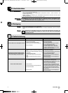
2.3.1 Front Panel
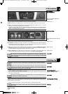
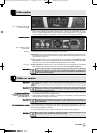
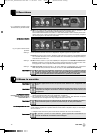
Fig. 1: Front panel controls and
indicator LEDs.
Refer to fig. 1.
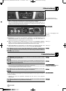
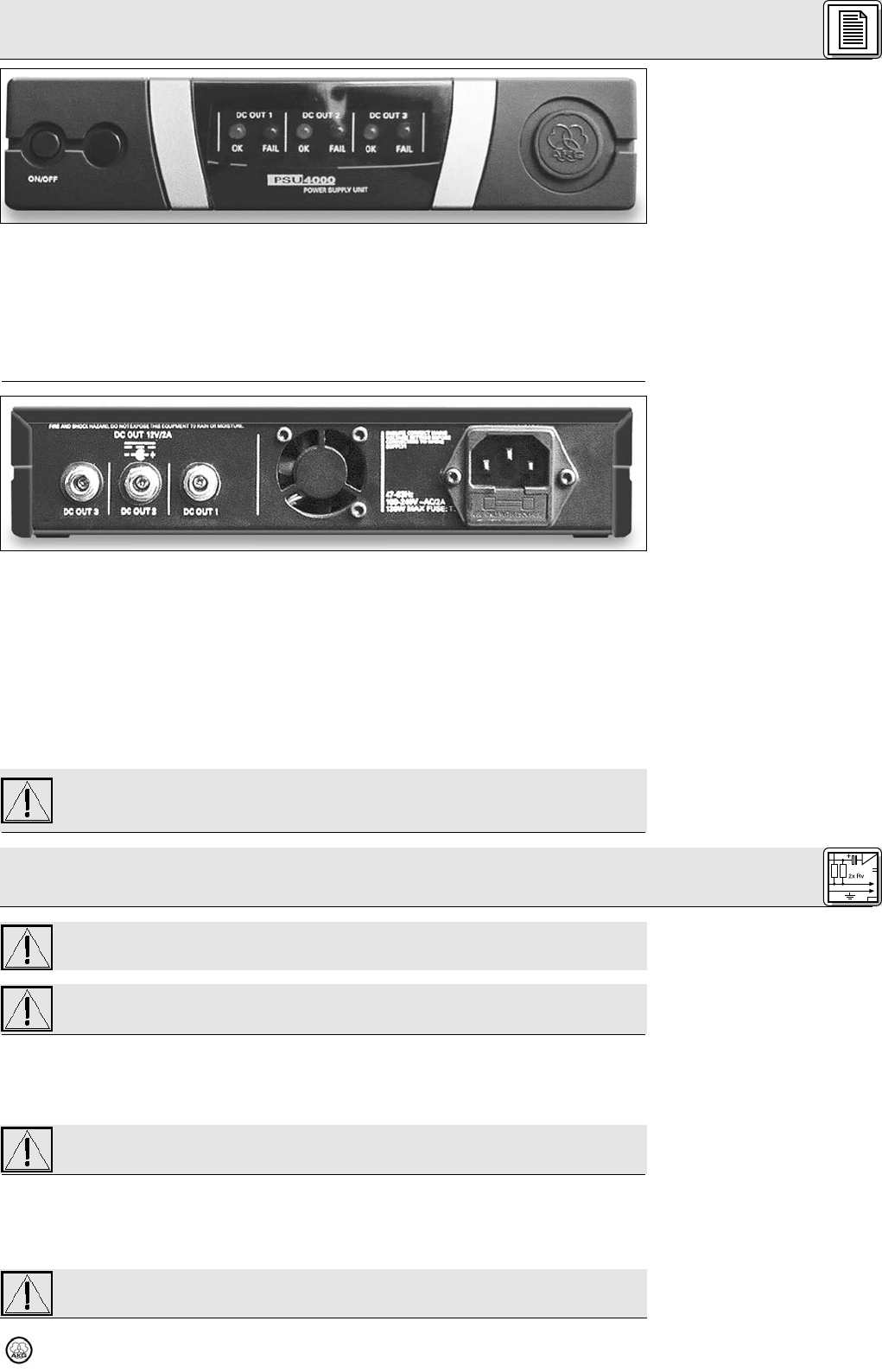
2.3.2 Rear Panel
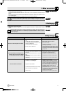
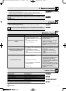
Fig. 2: Rear panel inputs and out-
puts.
Refer to fig. 2.
Refer to fig. 5.
Refer to fig. 5.
Important!
Important!
Important!
3.1 DC Connections
Connect PS 4000 with antenna
system to DC OUT 1 only!
Important!
3.2 Connecting to Power
Warning!
The power supply front panel provides the following controls and indicators:
ON/OFF: Press this key to switch power to the unit ON. Press again to switch power to the unit OFF.
DC OUT 1 - 3: The blue OK LED will be lit for as long as the assigned DC output DC OUT 1, 2, or 3 pro-
vides the correct supply voltage for active components.
Should the supply voltage at a DC output be shorted or fail (drop below 2 V), the output be over-
loaded, or the temperature of the unit exceed the acceptable level, the OK LED for that input will extin-
guish and the red FAIL LED be lit instead.
The PSU 4000 rear panel provides the following inputs and outputs:
IEC receptacle accepting the matching connector on the supplied power cable. The IEC receptacle
incorporates a standard fuse holder with a 2 A slow-blow fuse. The PSU 4000 uses a wide-range
power transformer for primary voltages from 90 VAC to 264 VAC.
DC OUT 1: DC output jack with a load capacity of up to 2.5 A for connecting a PS 4000 with an anten-
na system and up to four SR 4000 receivers (the receivers are powered via the antenna cables) or
one other WMS 4000 component (HUB 4000, HPA 4000, CU 4000).
DC OUT 2, DC OUT 3: DC output jacks with a load capacity of up to 2 A for connecting a WMS 4000
component (SR 4000, HUB 4000, HPA 4000, CU 4000, PS 4000 with no antenna system).
Make sure the total current consumption of all components connected to DC OUT 1 does
not exceed 2.5 A and the total current consumption of all components connected to DC
OUT 2 or DC OUT 3 does not exceed 2 A. Higher loads can cause damage to the PSU 4000
due to overheating.
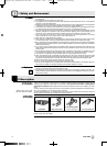
Do not connect the unit to power before you have made all audio and DC connections.
Check that the output voltage of the PSU 4000 is identical to the operating voltage of the
components your about to connect. Operating components on an incorrect voltage may
damage both the compponents and the PSU 4000.
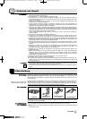
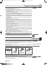
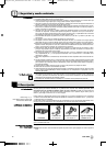
1. Use the supplied connecting cables to connect the DC OUT jacks on the rear panel of the PSU 4000
to the DC input jacks on the desired components.
2. Each connecting cable has a ferrite core attached near one end. Make sure to connect this end of
each cable to the PSU 4000.
Never plug a connecting cable into an unused DC OUT jack. The unused DC connector on
the cable may be shorted by metal parts.
The PSU 4000 features a wide-range power transformer for primary voltages from 90 VAC to 264 VAC.
Therefore, you can connect the unit to any power outlet with an AC voltage within this range and a fre-
quency between 47 Hz and 63 Hz.
1. Use the supplied power cable to connect the PSU 4000 to a convenient power outlet.
To avoid the risk of electric shock, make sure to connect the equipment to a grounded
power outlet.
7
PSU 4000
2 Description
3 Setting Up
BDA_PSU 4000_D030928:PSU 4000-Hex 11/30/2009 18:25 Seite 7 (Schwarz/Black Auszug)